Because RFL™ and Hubbell® have a policy of continuous product improvement, we reserve the right to change designs and specifications without notice.
4.9 CM4 PERFORMANCE DATA (RVU1 Group)
The RVU1 (Review 1) group functions indicate certain status information (Table 4-5). RVU1 status
functions, unlike BLNK group status functions, will always appear in the group. As explained in Table
4-5, the state of each RVU1 function is indicated by the ON/OFF indicator next to the the four-
character FUNCTION display on the CM4 module.
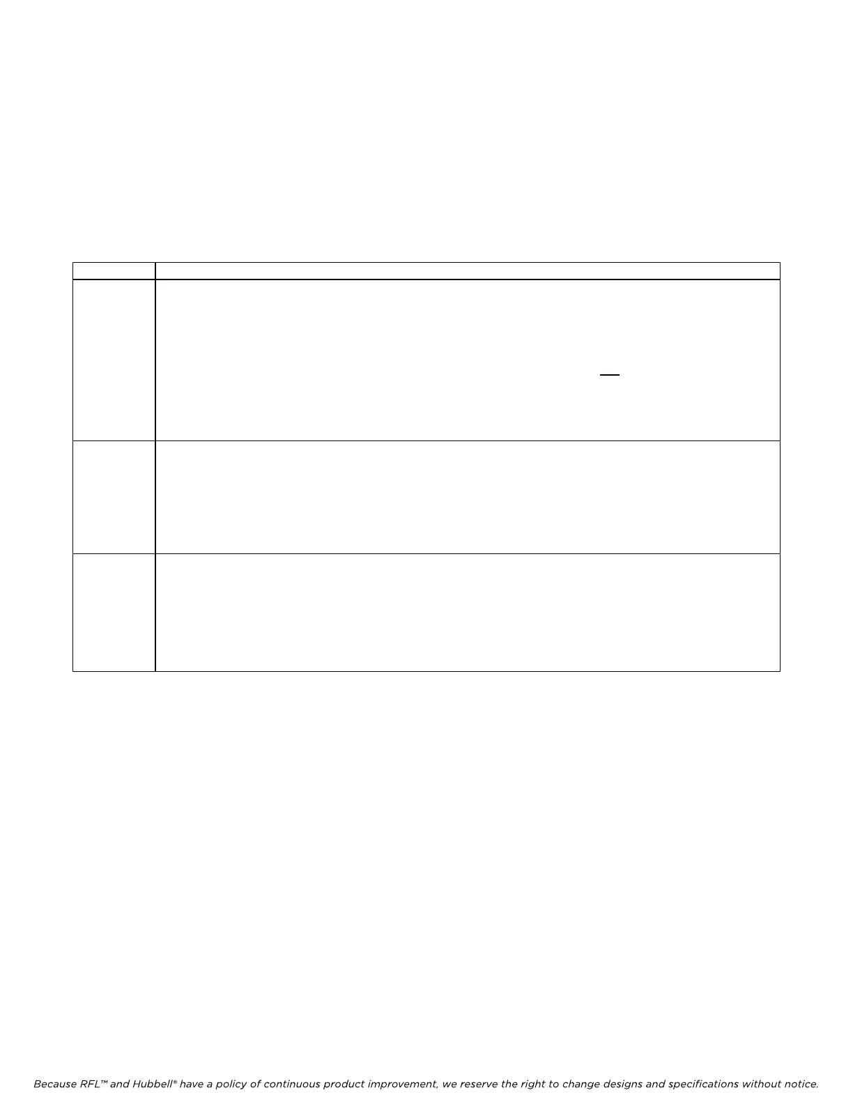
Table 4-5. RVU1 group
Function Description
TxRx Transmit/Receive Lock. When TxRx is displayed, the ON/OFF indicator shows whether the
transmit and receive bus clocks are locked:
Green This m
eans the transm
it and receive bus clocks are locked.
Red
This means the
transmit and receive bus clocks are not
locked.
This indication is the result of an approximate measurement. Proper test equipment should be used to verify
lock of bus clocks, if necessary.
RcLs Receiver Carrier Loss. When the Receiver Carrier Loss function is displayed, the bi-level ON/OFF
indicator will light to indicate the status of the T1 receiver carrier:
Green(top lit) The recei
ver has lost carrier.
Red(bottom
lit) The receiver h
as not lost carrier.
XsJt Excess Jitter. When XsJt is displayed, the ON/OFF indicator shows whether the receiver
jitter buffer depth has been exceeded. The factory-default buffer depth is 32 UI
p-p
, or ab
out 20.7 ms.
ON (green lit)This means the
jitter buffer depth has been exceeded.
OFF (red
lit)This m
eans the jitter buffer depth has not been exceeded.
M-DACS-T1 RFL Electronics Inc.
July 18, 2008 4-10 (973) 334-3100