Because RFL™ and Hubbell® have a policy of continuous product improvement, we reserve the right to change designs and specifications without notice.
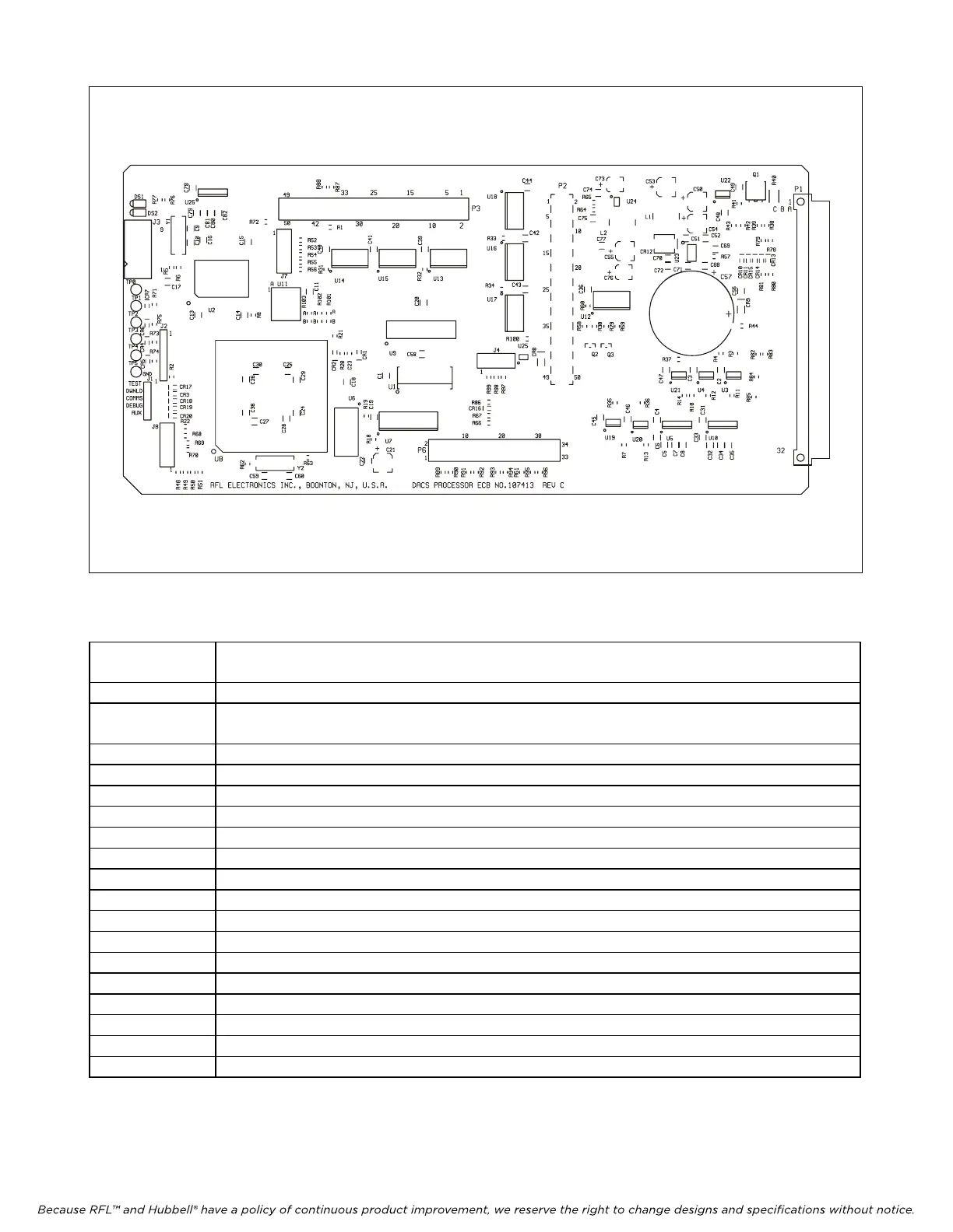
Figure 2-13. M-DACS Processor Module
Table 2-8. Processor module controls and indicators
Reference
Designation
Function
DS1 Green LED: ON = local power is good
DS2 Green LED: ON = normal, no local failure), OFF = processor board has detected a failure
of a locally monitored signal.
J1 For factory use only.
J2 For factory use only.
J3 For factory use only.
J4 For factory use only.
J6 For factory use only.
J7 For factory use only.
J8 For factory use only.
P2 Provides connections to P2 of Framer module.
P3 Provides connections to J1 of Redundant module.
P6 Provides connections to J3 of Redundant module.
TP0 For factory use only.
TP1 For factory use only.
TP2 For factory use only.
TP3 For factory use only.
TP4 For factory use only.
TP5 For factory use only.
M-DACS-T1 RFL Electronics Inc.
October 16, 2012 2-25 (973) 334-3100