Because RFL™ and Hubbell® have a policy of continuous product improvement, we reserve the right to change designs and specifications without notice.
RFL DA-121I RFL Electronics Inc.
February 10, 2000 12 (973)
334-3100
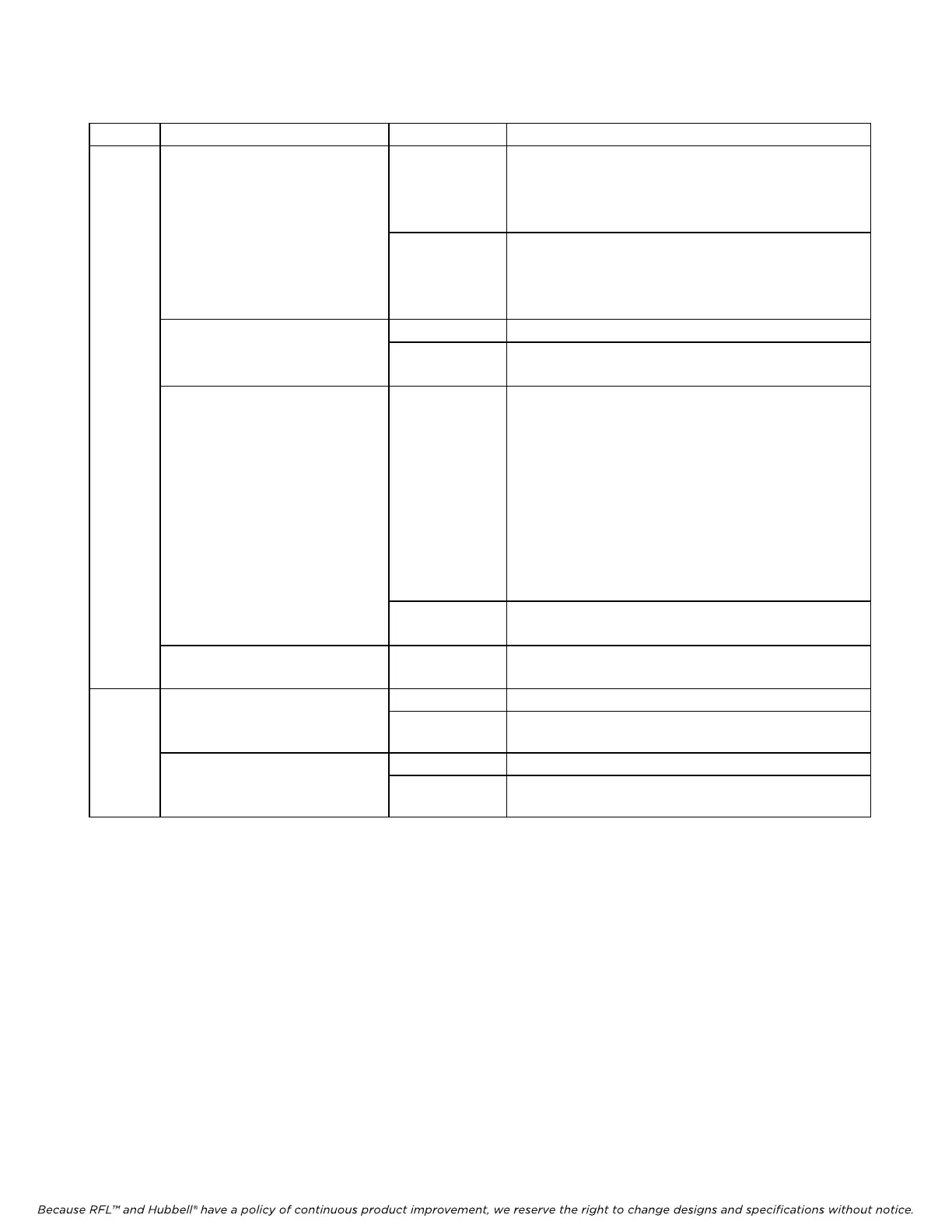
Table 4. Remote configuration settings (“P” codes) for T1 or E1 systems
P Code Digit(s) And Switch Equivalent Value
(1)
Description
P1 B 0 0 0 0 0 0 0 0
-
- - ↑ ↑ ↑ ↑ ↑
TIME SLOT SELECT
00001 to 11000
T1 Settin
gs
(2)
From left to right, these five bits represent the binary
value of the desired time slot between 1 through 24
in a T1 network. See Table 8 for a complete list of
these values.
00001 to 11111
E1 Settin
gs
(2)
From left to right, these five bits represent the binary
value of the desired time slot between 1 through 31
in an E1 network. See Table 8 for a complete list of
these values.
B 0 0 0 0 0 0 0 0 0 Sets CAS = OFF
- - ↑ - - - - -
CAS
1 Sets CAS = ON
B 0 0 0 0 0 0 0 0
↑ - - - - - - -
TERM
0 This
setting may be used only in a drop/insert
multiplexer. If the module is installed in a terminal
multiplexer, this digit should always be set to “1”.
If the module is installed in a drop/insert multiplexer,
set this digit to a “1” to transmit in the A direction
and receive from the B direction. Set this digit to “0”
to transmit in the B direction and receive from
the A
direct
ion.
(For guidelines on setting channel module direction,
refer to the IMUX 2000 instruction manual).
1 This setting is required when the module is installed in
a terminal multiplexer.
B 0 0 0 0 0 0 0 0
- ↑ - - - - - -
. . . Not used.
P2 B 0 0 0 0 0 0 0 0 0 Sets local loopback OFF
↑ - - - - - - -
LOCAL LOOPBACK
1 Sets local loopback ON
B 0 0 0 0 0 0 0 0 0 Sets remote loopback OFF
- ↑ - - - - - -
REMOTE LOOPBACK
1 Sets
remote loopback ON
1. These are the only legal values for setting the parameters. Setting any parameter to a value outside its specified
range will produce an unpredictable result.
2. The R
FL DA-121I automatically detects whether it is used in a T1 or E1 system.