Because RFL™ and Hubbell® have a policy of continuous product improvement, we reserve the right to change designs and specifications without notice.
RFL DS-961D RFL Electronics Inc.
October 14, 2004 9 (973)
334-3100
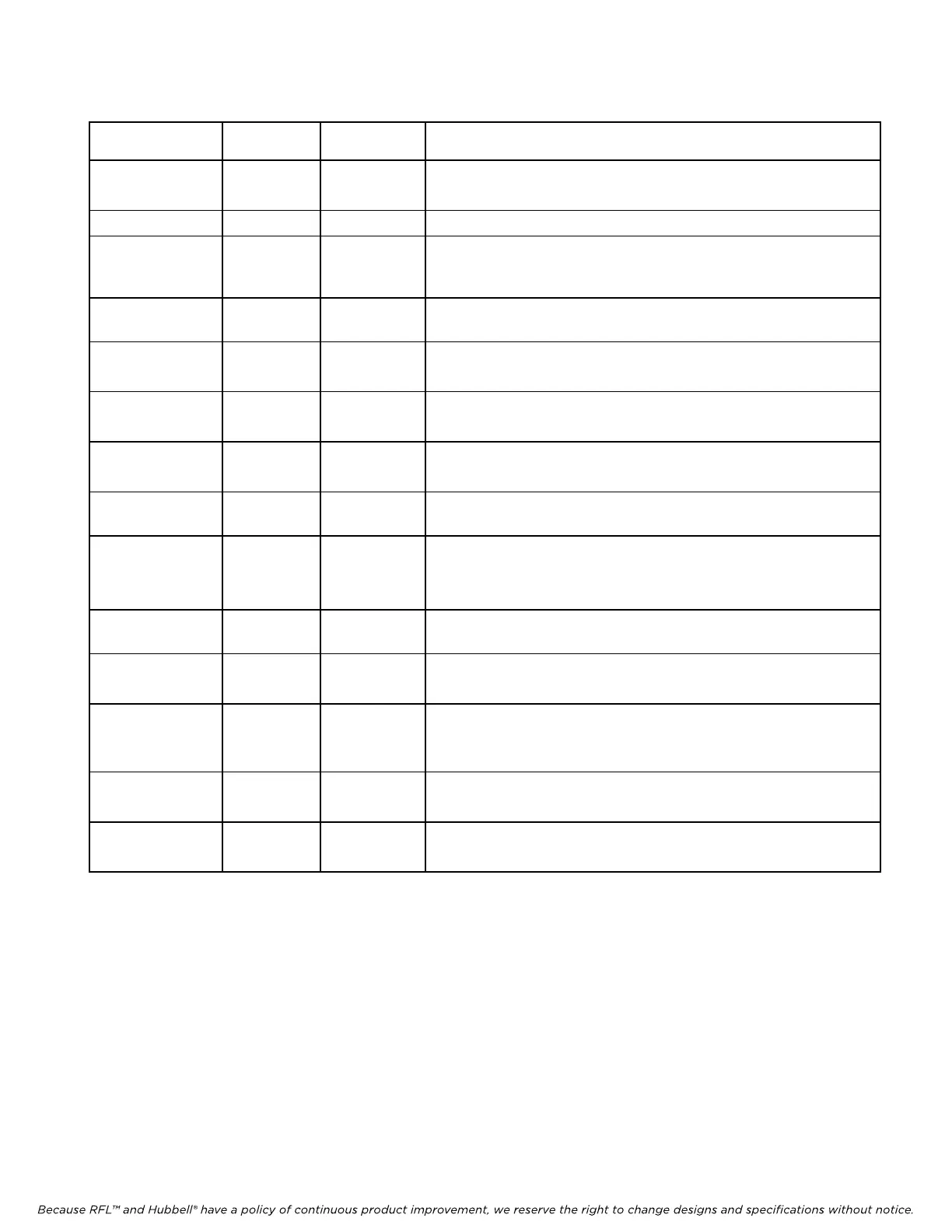
Table 2. Controls and indicators, RFL DS-961D Module
Co
ntrol/
Indicator
Label Setting Description
Jumper J1 NORMAL
3-CHANNEL
Sets module to 2-channel mode or 5-channel mode.
Sets module to 3-channel mode.
LED DS1 (green) TX BUSY . . . Indicates if one or more channels is transmitting.
LED DS3 (red) FRM . . . Indicates if the receiver side of the module cannot find the proper
framing bit in the receive time slot selected. A card level ALERT
signal is sent to the Common Module
LED DS4 (red) TX FAULT . . . Indicates if a fault is detected in the transmit circuitry of the logic
array. A card level ALARM signal is sent to the Common Module.
SW1-1 to SW1-6 . . . . . . Sets card address for remote access in accordance with Table 3.
(See Note 1 below).
SW1-7 . . . ON
OFF
Sets module to remote control (See Note 1 below).
Sets module to local control.
SW1-8 . . . ON
OFF
Module service is disabled.
Module service is enabled.
SW2-1 to SW2-5 TIME SLOT
SELECT
. . . Select time slot in accordance with Table 4.
SW2-6 TX A BUS
UP
DOWN
Operate via DI-B port in a drop/insert multiplexer (see page 14).
Operate in a terminal multiplexer, or via DI-A port in a drop/insert
multiplexer.
SW3-1 & SW3-2 RATE 1
RATE 2
. . . Select data rate in 5-Channel mode in accordance with Table 5.
SW3-3 SEL 9.6 UP
DOWN
Selects 2 or 3-Channel mode (Ports 1 & 2 = 19.2)
Selects 5-Channel mode
SW3-4 BUF IN UP
DOWN
Takes buffers out of circuit and sets module to use its internal timing
(See Note 2 below).
Places buffers in circuit and sets module to use DTE device timing.
SW3-5 to SW3-9 INV
A,B,C,D,E
UP
DOWN
Standard timing for selected channel.
Inverts timing for selected channel (See Note 3 below)
SW3-10 LOOP UP
DOWN
Turns loopback off (normal operation) .
Turns loopback on (See Note 4 below).
1. When this module is installed in a non-remote controllable multiplexer SW1-1 to SW1-7 must be OFF.
2. The input buffers must be used when the DTE device timing is in use, so this switch sets both of these
conditions.
3. These switches are active only when internal timing is selected (SW3-4).
4. When the loop switch is DOWN, all five receive channels are looped back into the transmitter (used for far
end loopback during end to end testing).