Because RFL™ and Hubbell® have a policy of continuous product improvement, we reserve the right to change designs and specifications without notice.
Table 5. Remote configuration settings (“P” codes)
Parameter Possible Settings
(1)
Description
SRVC ON Turn service on (enable module).
OFF Turn service off (disable module).
P01 1 to 24 Selects time slot(s).
P02
(2)
0 Module will transmit in A direction, receive from B direction.
1 Module will transmit in B direction, receive from
A direction.
P03
(3)
0 Enables E&M signaling per AT&T Publication 43801.
1 Disabl
es E&M signaling.
P04 0 Channel 2 off (one-channel operation).
1 Ch
annel 2 on (two-channel operation).
NOTES:
1. These are the only legal values for setting the parameters. Setting any parameter to a value outside its specified
range will produce an unpredictable result.
2. If the multiplexer is a Terminal version, P02 should always be set to zero. If the multiplexer is a Drop/Insert
version, set it to 0 to transmit in the A direction and receive from the B direction. Set it to 1 to transmit in the B
direction and receive from the A direction. Refer to the IMUX 2000 instruction manual for guidelines on setting
channel module direction.
3. With E&M signaling enabled, the logic circuitry robs one bit from the transmission every sixth frame of the frame
format to use for signaling. If signaling is disabled, all bits are used for voice encoding. Signaling should be
disabled when using a voice-grade data modem over a voice-frequency circuit.
"S" codes appear in response to a "STATUS?" query in the following format:
*OK
CHANNEL CARD 3, TYPE 64
S01 = 00 (B00000000);
The "S" code will be a number between 0 and 15, inclusive. The binary representation is more useful
here than the decimal; the four least significant digits of the binary number represent the on/off status
of the "E" and "M" leads, as shown in Table 6. The four most-significant digits are not used.
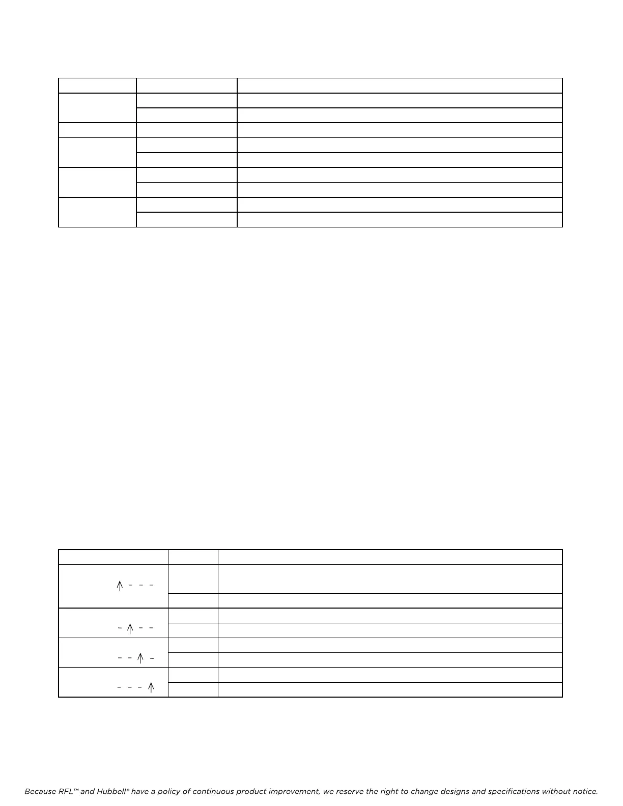
Table 6. Remote Status Messages (S codes)
Position Value Description
B 0 0 0 0 0 0 0 0 0 E2 lead is idle.
1 Signaling is enabled and the E2 lead is active.
B 0 0 0 0 0 0 0 0 0 E1 lead is idle.
1 Signaling is enabled and the E1 lead is active.
B 0 0 0 0 0 0 0 0 0 M2 lead is idle.
1 M2 lead is active.
B 0 0 0 0 0 0 0 0 0 M1 lead is idle.
1 M1 lead is active.
RFL VF-5A RFL Electronics Inc.
June 28, 2005 21 (973)
334-3100