Because RFL™ and Hubbell® have a policy of continuous product improvement, we reserve the right to change designs and specifications without notice.
RFL VF-5C RFL Electronics Inc.
October 8, 2012 38 (973)
334-3100
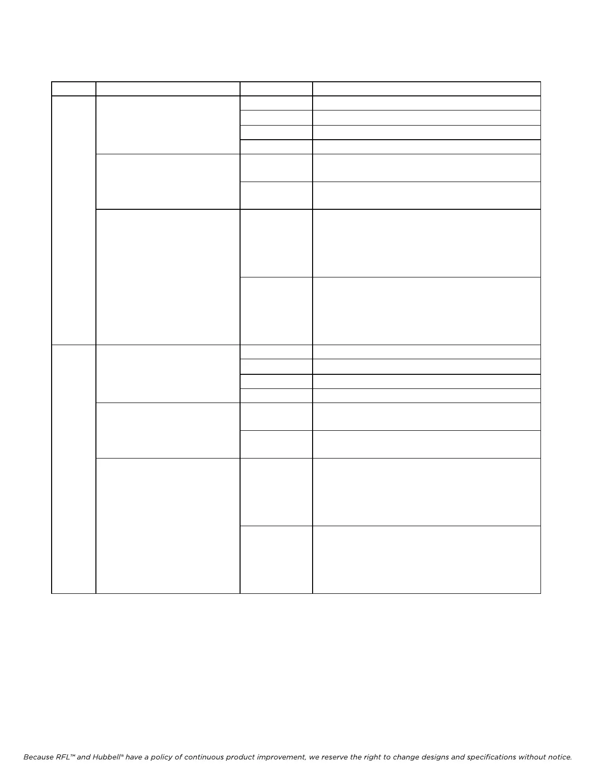
Table 6. Remote configuration settings (“P” codes)
P Code Digit(s) And Switch Equivalent Value
(1)
Description
P1
B 0 0 0 0 0 0 0 0
00 OFF
↑ ↑ - - - - - -
01 R
emote
CH1 LOOPBACK MODE
10 Local
11 2713 Hz mode
B 0 0 0 0 0 0 0 0
- - ↑ - - - - -
0 Ch1 = DI-B
CH1 TERMINAL
1 Ch1 = Term
inal/DI-A
B 0 0 0 0 0 0 0 0
- - - ↑ ↑ ↑ ↑ ↑
CH1 TIMESLOT
00001 t
o 11000
T1 Settin
gs
From left to right, these five bits represent the binary
value of the desired time slot between 1 through 24
in a T1 network. See Table 8 for a complete list of
these values.
00001 to 11111
E1 Settin
gs
From left to right, these five bits represent the binary
value of the desired time slot between 1 through 31
in an E1 network. See Table 8 for a complete list of
these values.
P2
B 0 0 0 0 0 0 0 0
00 OFF
↑ ↑ - - - - - -
01 R
emote
CH2 LOOPBACK MODE
10 Local
11 2713 Hz mode
B 0 0 0 0 0 0 0 0
- - ↑ - - - - -
0 Ch2 = DI-B
CH2 TERMINAL
1 Ch2 = Term
inal/DI-A
B 0 0 0 0 0 0 0 0
- - - ↑ ↑ ↑ ↑ ↑
CH2 TIMESLOT
00001 t
o 11000
T1 Settin
gs
From left to right, these five bits represent the binary
value of the desired time slot between 1 through 24
in a T1 network. See Table 8 for a complete list of
these values.
00001 to 11111
E1 Settin
gs
From left to right, these five bits represent the binary
value of the desired time slot between 1 through 31
in an E1 network. See Table 8 for a complete list of
these values.
>> ta
ble continues on next page <<
1. These are the only legal values for setting the parameters. Setting any parameter to a value outside its
specified range will produce an unpredictable result.