Because RFL™ and Hubbell® have a policy of continuous product improvement, we reserve the right to change designs and specifications without notice.
RFL VF-16B RFL Electronics Inc.
January 17, 2007 16 (973) 334-3100
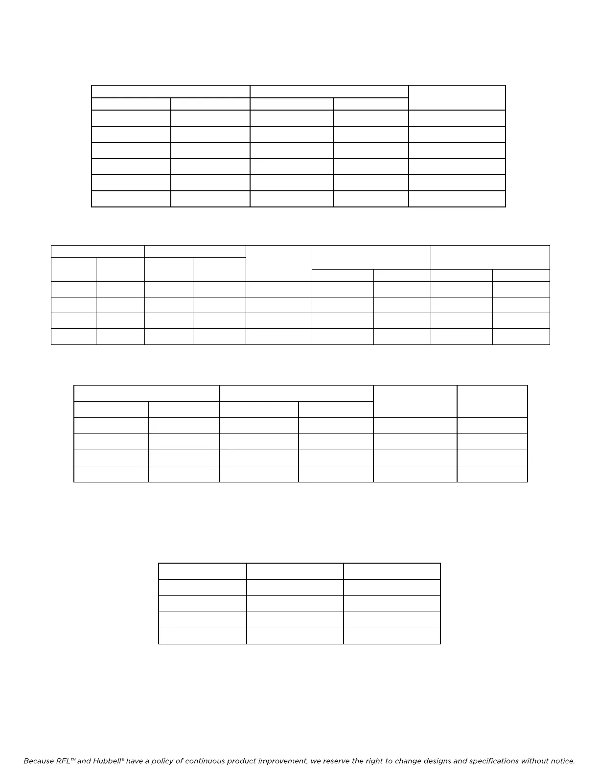
Table 3. Transmit/receive level settings, RFL VF-16B modules
Channel 1 Channel 2
Transmit Level Receive Level Transmit Level Receive Level
Value
SW4-1 SW5-1 SW7-1 SW8-1 +/-
SW4-2 SW5-2 SW7-2 SW8-2 8dB
SW4-3 SW5-3 SW7-3 SW8-3 4dB
SW4-4 SW5-4 SW7-4 SW8-4 2dB
SW4-5 SW5-5 SW7-5 SW8-5 1dB
SW4-6 SW5-6 SW7-6 SW8-6 0.5dB
Table 4. Ring Voltage switch settings, RFL VF-16B modules
Channel 1 Channel 2 AC
Ring
Channel 1
Ring Voltage Offset
Channel 2
Ring Voltage Offset
SW6-1 SW6-2 SW9-1 SW9-2 Voltage SW6-3 OFF SW6-3 ON SW9-3 OFF SW9-3 ON
OFF OFF OFF OFF
40.5 0 Vdc 30 Vdc 0 Vdc 30 Vdc
OFF ON OFF ON
45 0 Vdc 20 Vdc 0 Vdc 20 Vdc
ON OFF ON OFF
53 0 Vdc 10 Vdc 0 Vdc 10 Vdc
ON ON ON ON
63.5 0 Vdc 0 Vdc 0 Vdc 0 Vdc
Table 5. Ring Delay switch settings, RFL VF-16B modules
Channel 1 Channel 2
SW6-6 SW6-7 SW9-6 SW9-7
Off-Hook
Ring Delay
On-Hook
Ring Delay
OFF OFF OFF OFF No Delay No Delay
OFF ON OFF ON 200ms 400ms
ON OFF ON OFF 300ms 600ms
ON ON ON ON 400ms 800ms
Note: Ring Delay is used to avoid erroneous ringing during network disturbances. For this reason, several settings
have been made available in order to maintain compatibility with certain phone system features (e.g. distinctive
ringing).
Table 6. Loopback Mode Settings, RFL VF-16B modules
SW10-1 SW10-2 Loopback Mode
UP UP Analog
UP DOWN Full Analog
DOWN UP Digital
DOWN DOWN Dual Analog
Note: See page 17 and Figure 7 for a description of loopback modes.