Because RFL™ and Hubbell® have a policy of continuous product improvement, we reserve the right to change designs and specifications without notice.
FUNCTIONAL DESCRIPTION
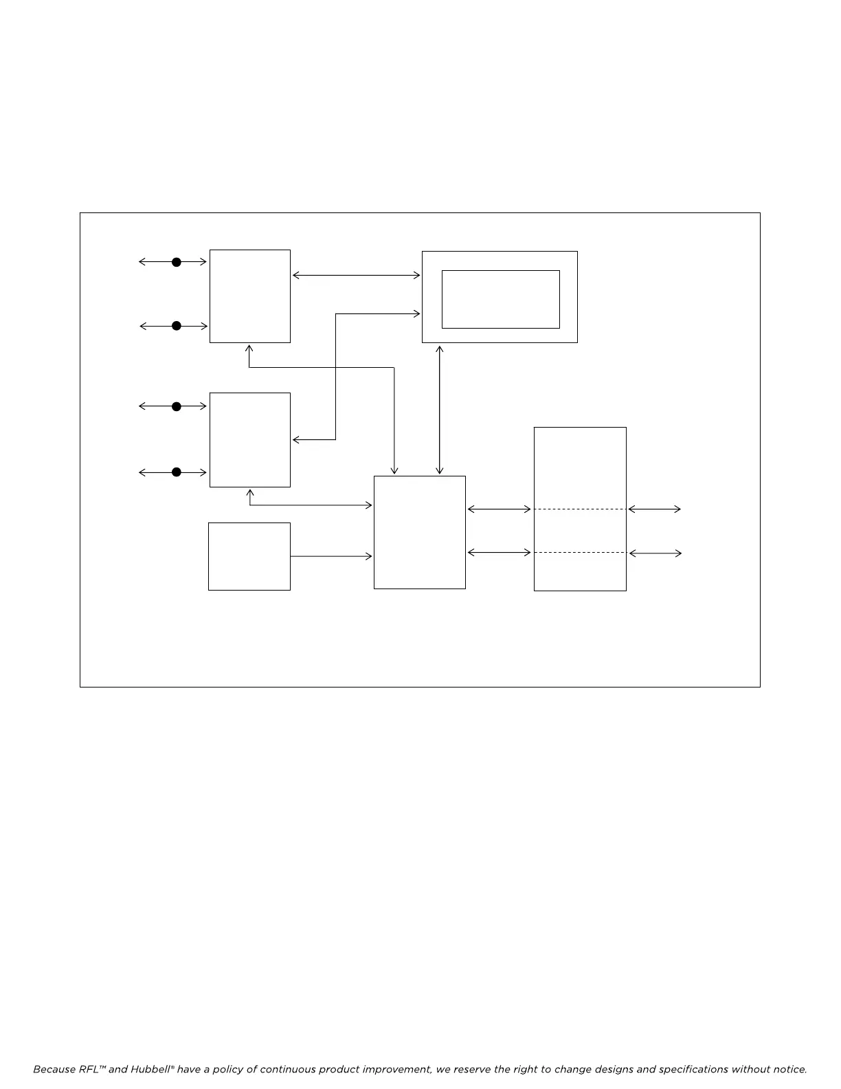
Figure 8 is a functional block diagram of the RFL VF-16B. The module uses a Subscriber Line
Interface Circuit (SLIC). At the RFL VF-16B (station end), the SLIC simulates a Central Office,
supplying loop current and ringing voltage to the external phone circuit.
TIP
CH1
RING
TIP
CH2
RING
SLIC CH1
SLIC CH2
DIP
SWITCHES
SW1 to SW10
PCM DATA
LOGIC
ARRAY
BUS
DRIVERS
AND
RECEIVERS
PCM DATA
CONFIG/STATUS
INFO
CONFIG/STATUS
INFO
u-CONTROLLER
CALL PROCESSING
ENGINE
TO/FROM
IMUX 2000
DATA BUS
TO/FROM
IMUX 2000
CONTROL
BUS
TP
TP
TP
TP
Figure 8. Functional block diagram, RFL VF-16B module
The PCM output from the SLIC is passed to a logic array. This array multiplexes the voice bits
together with signaling bits provided by the microcontroller (On-Hook, Off-Hook, Ringing, No
Ringing). Once multiplexed, this combined information is placed into the user-selected time slot of the
transmit bus on the multiplexer's backplane.
On the receive side, the logic array takes the incoming data from the selected time slot, demultiplexes
it, and passes the voice bits to the SLIC and the signaling bits to the microcontroller.
The SLIC is a highly integrated device that combines the functions of a SLIC, volume control,
CODEC, DC-to-DC converter, ring generator, call progress tone generator, and loop supervision
circuit. The SLIC is configured and controlled by the microcontroller.
RFL VF-16B RFL Electronics Inc.
January 17, 2007 23 (973)
334-3100