Because RFL™ and Hubbell® have a policy of continuous product improvement, we reserve the right to change designs and specifications without notice.
125V
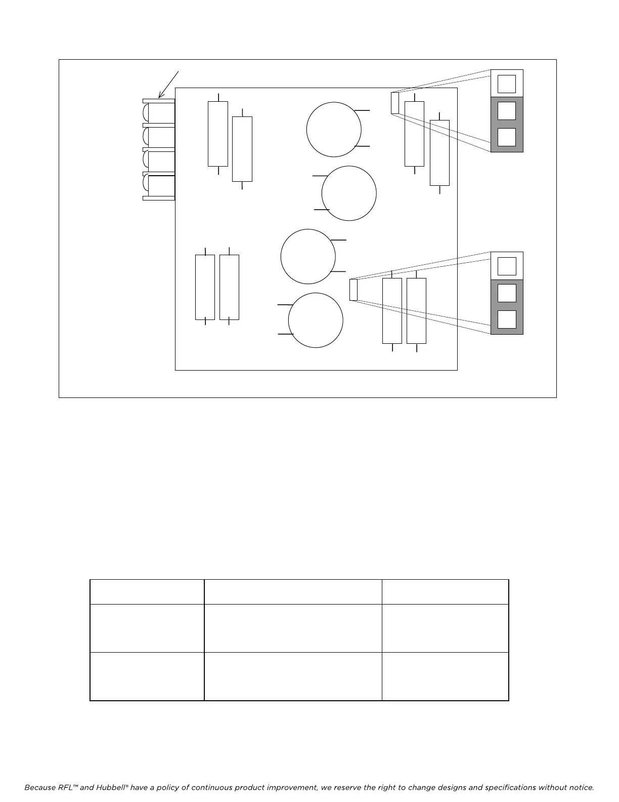
48V
125V
48V
INPUT TERMINAL BLOCK
J5
J4
For 48V OPERATION, JUMPERS SHALL BE LOCATED AS SHOWN
Figure 5. Location and use of voltage control jumpers on a typical I/O adapter module input board
4. Once the I/O adapter module has been selected, check the settings of the voltage control
jumpers located on the I/O adapter module input board(s). All eight versions of the I/O
module input boards shown in Figure 5 are identical, with the exception of the placement of
the two voltage control jumpers J4 and J5. Note the location of these jumpers in Figure 5.
For 48V operation both jumpers must be in the 48V position. For 125V
operation both jumpers must be in the 125V position. The 250V modules
should have both jumpers in the 125V position. See Table 2.
Table 2. Voltage control jumper settings
I/O Adapter Module
part number
I/O Adapter Module type J4 and J5 jumper position
105770-2
105770-4
2 function 48/125V solid state*
4 function 48/125V solid state
48V position
for 48V operation,
105740-2
105740-4
2 function 48/125V relay*
4 function 48/125V relay
125V position
for 125V operation
105770-3
105770-5
2 function 250V solid state*
4 function 250V solid state
125V position
105740-3
105740-5
2 function 250V relay*
4 function 250V relay
for 250V operation
* See NOTE on page 21 for 2 function systems.
RFL DS-TT RFL Electronics Inc.
January 31, 2008 9 (973)
334-3100