Because RFL™ and Hubbell® have a policy of continuous product improvement, we reserve the right to change designs and specifications without notice.
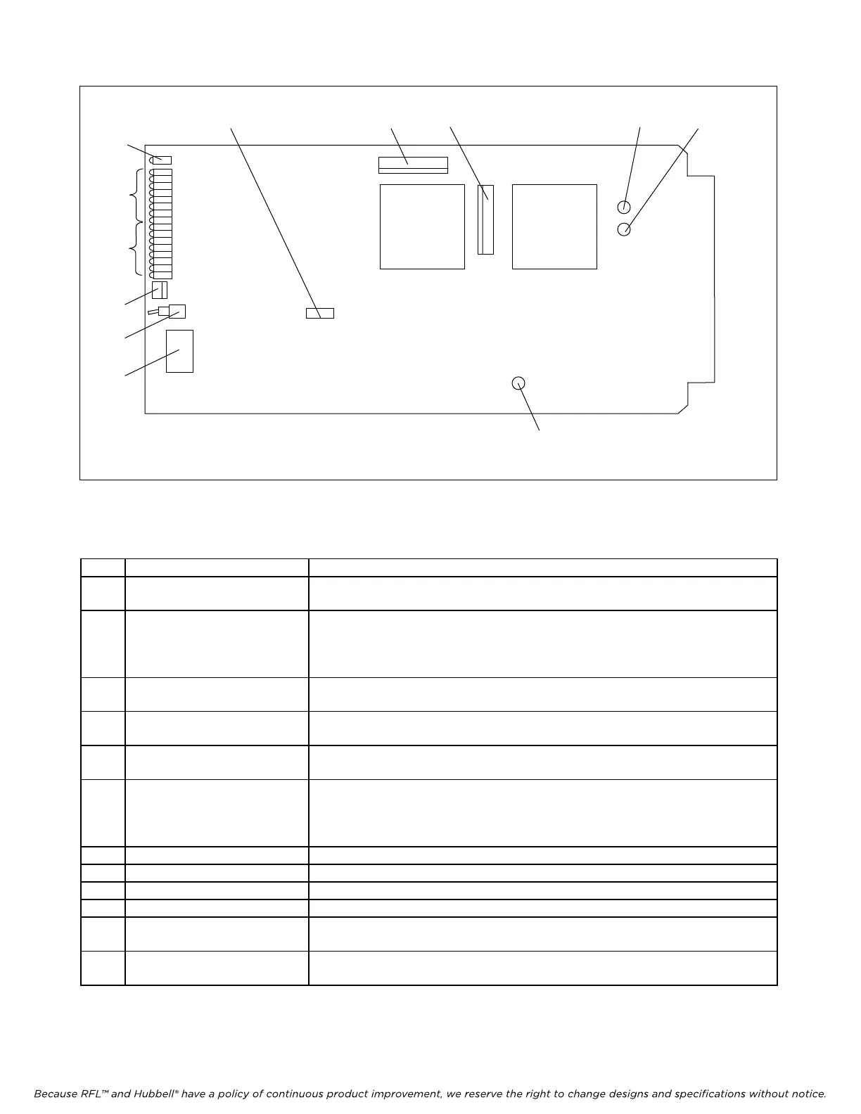
Figure 5. Controls and indicators, Status Module
TP1
10
129 8
11
6
J3
TP2
TP3
DS17
DS1
DS16
J1
SW2
SW1
TEST
RUN
J4
5
1
2
7
3
4
Table 1. Controls and indicators, Status Module
Item Name/Description Function
1 DIP Switch SW1 Sets SCB address in accordance with the codes shown in Table 2.
2 Toggle Switch SW2 Keeps outputs from changing after the switch is placed in the Locked position.
UP - Output Unlocked - In Operation
DOWN - Output Locked - Out Of Operation
3 LED Indicators DS1 to DS7
(red)
When lit, indicates that the corresponding inputs or outputs are active.
4 LED Indicators DS8 to DS16
(red)
When lit, indicates that the corresponding inputs or outputs are active.
5 LED Indicator DS17
(red)
Turns OFF upon receipt of a properly framed and addressed message
6 Jumper J2 Used to select TEST or RUN modes
RUN mode - used for normal operation
TEST mode - used for factory testing
7 Jack J1 RS232 interface
8 Jack J3 Used for factory testing only
9 Jack J4 Used for factory testing only
10 Test Point TP1 Ground
11 Test Point TP2 When = 1, a valid address has been received (For factory test only)
12 Test Point TP3 When = 1, a valid frame has been received (For factory test only)
RFL Status Module RFL Electronics Inc.
July 15, 2007 9 (973)
334-3100