Because RFL™ and Hubbell® have a policy of continuous product improvement, we reserve the right to change designs and specifications without notice.
RFL TMX/TMR RFL Electronics Inc.
January 25, 2012 34 (973)
334-3100
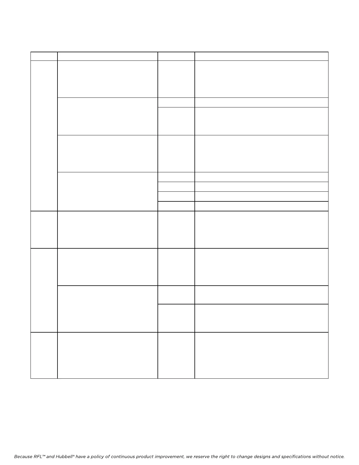
Table 17. continued - Remote configuration settings (“P” codes) for RFL TMR module
P Code Digit(s) And Switch Equivalent Value
(1)
Description
P7 B 0 0 0 0 0 0 0 0
- - - - -
↑ ↑ ↑
ANALOG CHANNEL 2 FIXED
DATA LEVEL SELECTOR
000 to 111 See Table 18
B 0 0 0 0 0 0 0 0 0 Connects analog channel 1 to live data
- - - - ↑ - - -
ANALOG CHANNEL 2
FIXED LEVEL SWITCH
1 Forces analog channel 1 data to fixed level
at the D/A converter.
B 0 0 0 0 0 0 0 0
- - ↑ ↑ - - - -
ANALOG CHANNEL 2 LOSS
OF SIGNAL OUTPUT SELECTOR
00 to 11 See Table 19
B 0 0 0 0 0 0 0 0 00 Output gain = 1
↑ ↑ - - - - - -
01 Output gain = 1/2
ANALOG CHANNEL 2
10 Output
gain = 1/4
OUTPUT GAIN SELECTOR
11 Output
gain = 1/8
P8 B 0 0 0 0 0 0 0 0
↑ ↑ ↑ ↑ ↑ ↑ ↑ ↑
ANALOG CHANNEL 2
LS BYTE OF TRANSFER RATIO
00000000 to
11111111
(0 to 255
decimal)
See Table 20
P9 B 0 0 0 0 0 0 0 0
- ↑ ↑ ↑ ↑ ↑ ↑ ↑
ANALOG CHANNEL 2
MS BYTE OF TRANSFER RATIO
0000000 to
1111111
(0 to 127
decimal)
See Table 20
B 0 0 0 0 0 0 0 0
↑ - - - - - - -
0 Positive polarity offset
ANALOG CHANNEL 2
POLARITY OF
OUTPUT OFFSET
1 Negati
ve polarity offset
P10 B 0 0 0 0 0 0 0 0
↑ ↑ ↑ ↑ ↑ ↑ ↑ ↑
ANALOG CHANNEL 2
MAGNITUDE OF
OUTPUT OFFSET
00000000 to
11111111
(0 to 255
decimal)
See Table 16