Because RFL™ and Hubbell® have a policy of continuous product improvement, we reserve the right to change designs and specifications without notice.
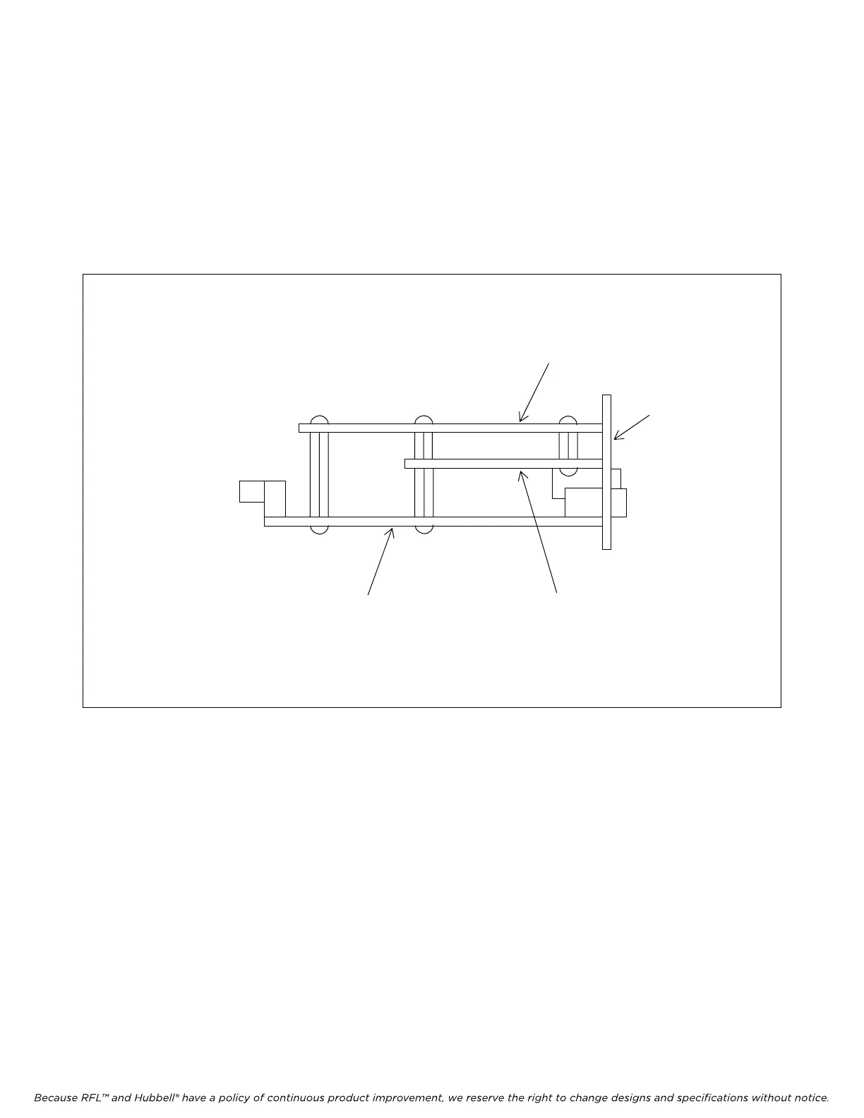
As shown in Figure 2, the MA-490 is made up of three boards, consisting of Board A, Board B and
Board C. Board A contains two DB9 connectors and has some signals that are needed in other
applications. Board B, contains a 3.3-volt regulator, an octal bi-directional transceiver, and a 5.0-volt,
ramp power supply circuit with a hot swap controller. The hot swap controller allows safe board
insertion and removal from a live IMUX backplane without interruption of the DS1 or any other DS0.
The hot swap controller also provides a reset signal to the Rabbit 3000 processor after the MA490 is
powered up. Board C is an Ethernet Core Module RCM3010 board with a Rabbit 3000 microprocessor
with a fully integrated 10Base-T Ethernet interface. Refer to Figure 3 for additional information.
BOARD B
BOARD A
BOARD C
REAR
PANEL
Figure 2. Side view of MA-490 showing location of Boards A, B and C.
RFL MA-490 Telnet I/O RFL Electronics Inc.
March 6, 2007 3 (973)
334-3100