Because RFL™ and Hubbell® have a policy of continuous product improvement, we reserve the right to change designs and specifications without notice.
15. (continued).
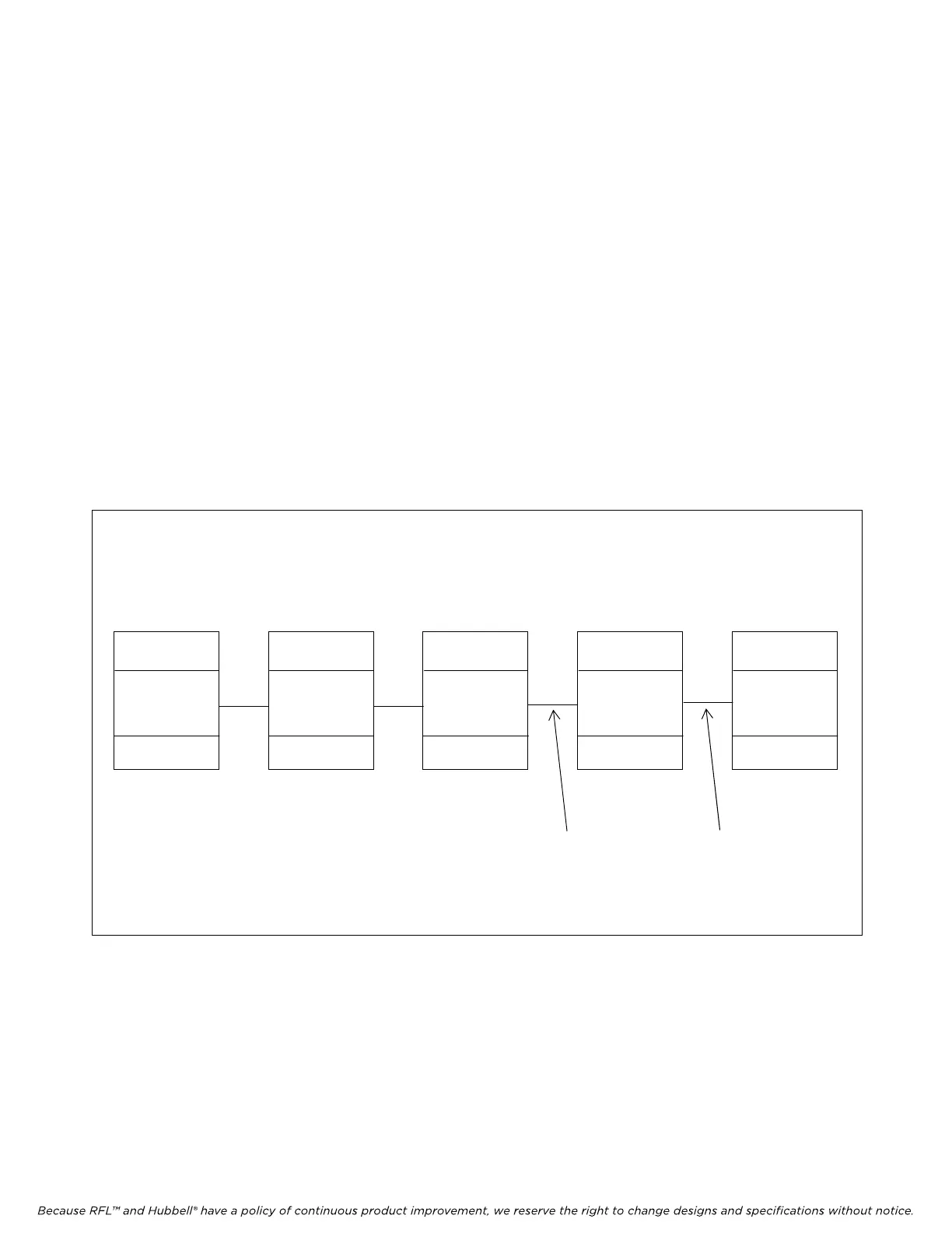
If some of the nodes in a T1/E1 network have an NCM, and others do not as shown in Figure 7,
the address Pass Setting will be set differently at some of the nodes. In Figure 7, nodes 1, 2 and
3 have NCM modules, and nodes 4 and 5 do not have NCM modules. This network requires
that at nodes 1 and 2, SW7 is set as follows:
Place SW7-1 in the DOWN position
Place SW7-2 in the UP position
And at node 3, SW7 is set as follows:
Place SW7-1 in the UP position
Place SW7-2 in the DOWN position
Additionally all 5 nodes must have the CM setting UNIV = ON to enable the FDL path. This
allows a user to “transparently” communicate to all nodes regardless of which node the PC is
connected to. If the PC is connected to node 1, 2 or 3, a user can “talk to” nodes 1, 2 or 3 via
the NCM path, and “talk to” nodes 4 and 5 over the FDL path. If the PC is connected to nodes
4 or 5, communication to all nodes is over FDL.
IMUX 2000
NCM in NMS mode
(CM address = 1)
(NCM address = 1)
SW7-1 = DOWN
SW7-2 = UP
Pass 1
IMUX 2000
NCM in NMS mode
(CM address = 2)
(NCM address = 2)
SW7-1 = DOWN
SW7-2 = UP
Pass 2
Node 1 Node 2 Node 3 Node 4 Node 5
IMUX 2000
NCM in NMS mode
(CM address = 3)
(NCM address = 3)
SW7-1 = UP
SW7-2 = DOWN
Pass ≥3
IMUX 2000
(CM address = 4)
IMUX 2000
(CM address = 5)
FDL FDL
Figure 7. Network example with nodes 1, 2 and 3 having an NCM module, and nodes 4 and 5 without NCM modules
RFL NCM RFL Electronics Inc.
November 1, 2012 11 (973) 334-3100