BIT SWITCHES
SM 21 B620
Fax Option
B620
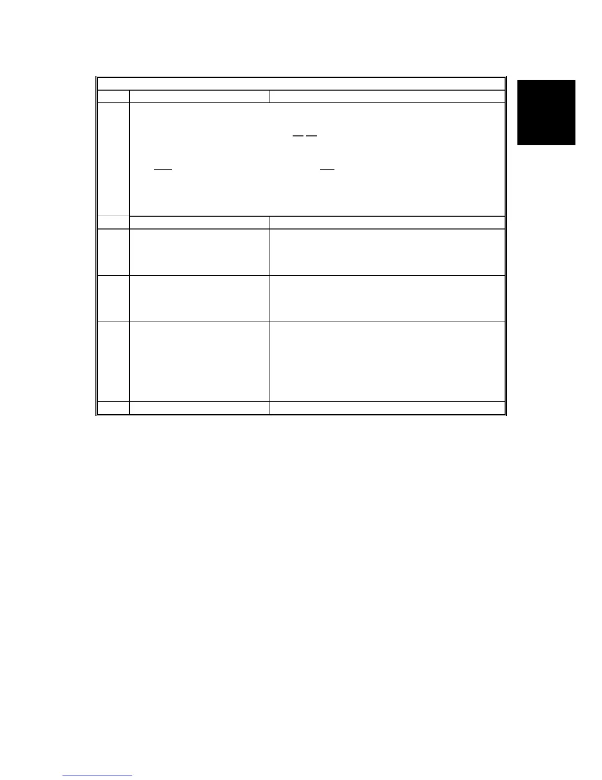
System Switch 00 SP No. 1-101-001
No FUNCTION COMMENTS
2
Rx level calculation
Example: 0000 32 V34 288/264 L 01
00 03 04
The four-digit hexadecimal value (N) after “L” indicates the rx level.
The high
byte is given first, followed by the low byte. Divide the decimal value of N by
-16 to get the rx level.
In the above example, the decimal value of N (= 0100 [H]) is 256.
So, the actual rx level is 256/-16 = -16 dB
3 Not used Do not change the setting.
4
Line error mark on the
received page
0: Disabled
1: Enabled
If this bit is 1, a mark will be printed on the left edge
of the page at any place where a line error occurred
in the data. Such errors are caused by a noisy line
for example.
5
G3 communication parameter
display
0: Disabled
1: Enabled
This is a fault-finding aid. The LCD shows the key
parameters (see below). This is normally disabled
because it cancels the CSI display for the user.
Be sure to reset this bit to 0 after testing.
6
Protocol dump list output after
each communication
0: Off
1: On
This is only used for communication
troubleshooting. It shows the content of the
transmitted facsimile protocol signals. Always reset
this bit to 0 after finishing testing.
If system switch 09 bit 6 is at “1”, the list is only
printed if there was an error during the
communication.
7 Not used Do not change the setting.