SCANNER UNIT
B121 Series/B259 Series 3-12 SM
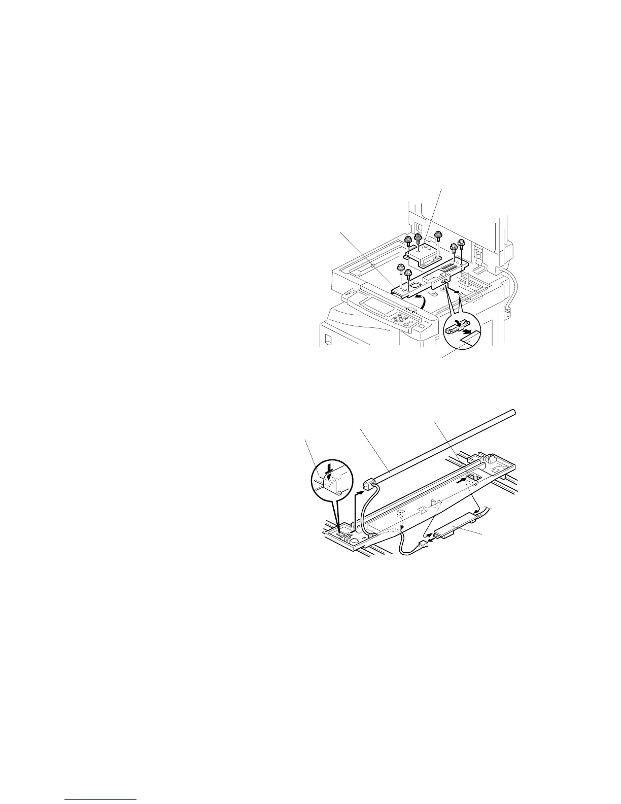
3.4.2 LENS BLOCK
CAUTION:
1) Do not touch the paint-locked screws on the lens block. The position
of the lens assembly (black part) is adjusted before shipment.
2) Do not grasp the PCB or the lens assembly when handling the lens
block. The lens assembly may slide out of position.
1. Exposure glass ( 3.4.1)
2. Lens cover [A] ( x 5)
3. Disconnect the flat cable [B].
4. Lens block [C] ( x 4).
After installing a new lens block, adjust
the image quality ( 3.13).
3.4.3 LAMP STABILIZER BOARD AND EXPOSURE LAMP
1. Operation panel ( 3.3.4)
2. Exposure glass ( 3.4.1)
3. Slide the first scanner to a
position where the front end of the
lamp is visible.
4. Place one hand under the lamp
stabilizer board [A] and release
the hook [B].
5. Lamp stabilizer board ( x 2)
6. Press the plastic latch [C] and
push the front end of the lamp
toward the rear.
7. Lamp [D] (with the cable)
B121R951.WMF
B121R910.WMF
[B]
[C]
[A]
[A]
[B]
[C]
[D]