ONE-BIN TRAY INSTALLATION
B121 Series/B259 Series 1-22 SM
1.8 ONE-BIN TRAY INSTALLATION
1.8.1 ACCESSORY CHECK
Check the quantity and condition of the accessories.
No. Description Q’ty
1 Installation procedure 1
2 One-bin sorter 1
3 Exit tray 1
4 Tapping screw M3 x 6 1
1.8.2 INSTALLATION PROCEDURE
CAUTION
Unplug the machine power cord before starting the following procedure.
The One –Bin Tray cannot be installed on the B121 or B259 models.
• For the B122 and B260 models, begin this procedure at step 3.
• For the B123 and B261 models, begin this procedure at step 1.
NOTE: If a B260 or B261 model has been pre-configured at the factory to be a
scanner/printer/fax (spf) configuration, begin this procedure at step 14.
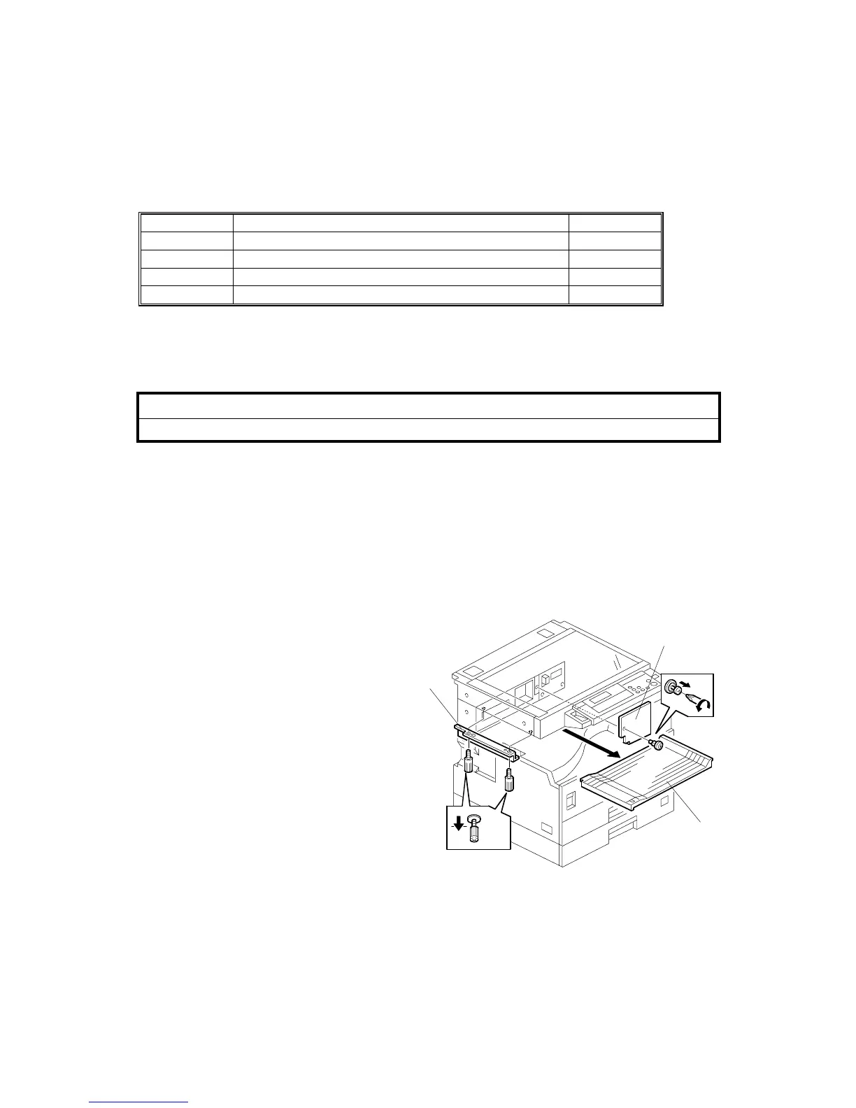
1. Remove the inverter tray [A].
2. Remove the rail [B]
(2 knob screws).
3. Remove the cover [C] (1 screw).
B621I902.WMF
[A]
[B]
[C]
⇒
Rev. 10/2005