KEY COUNTER INSTALLATION
B121 Series/B259 Series 1-32 SM
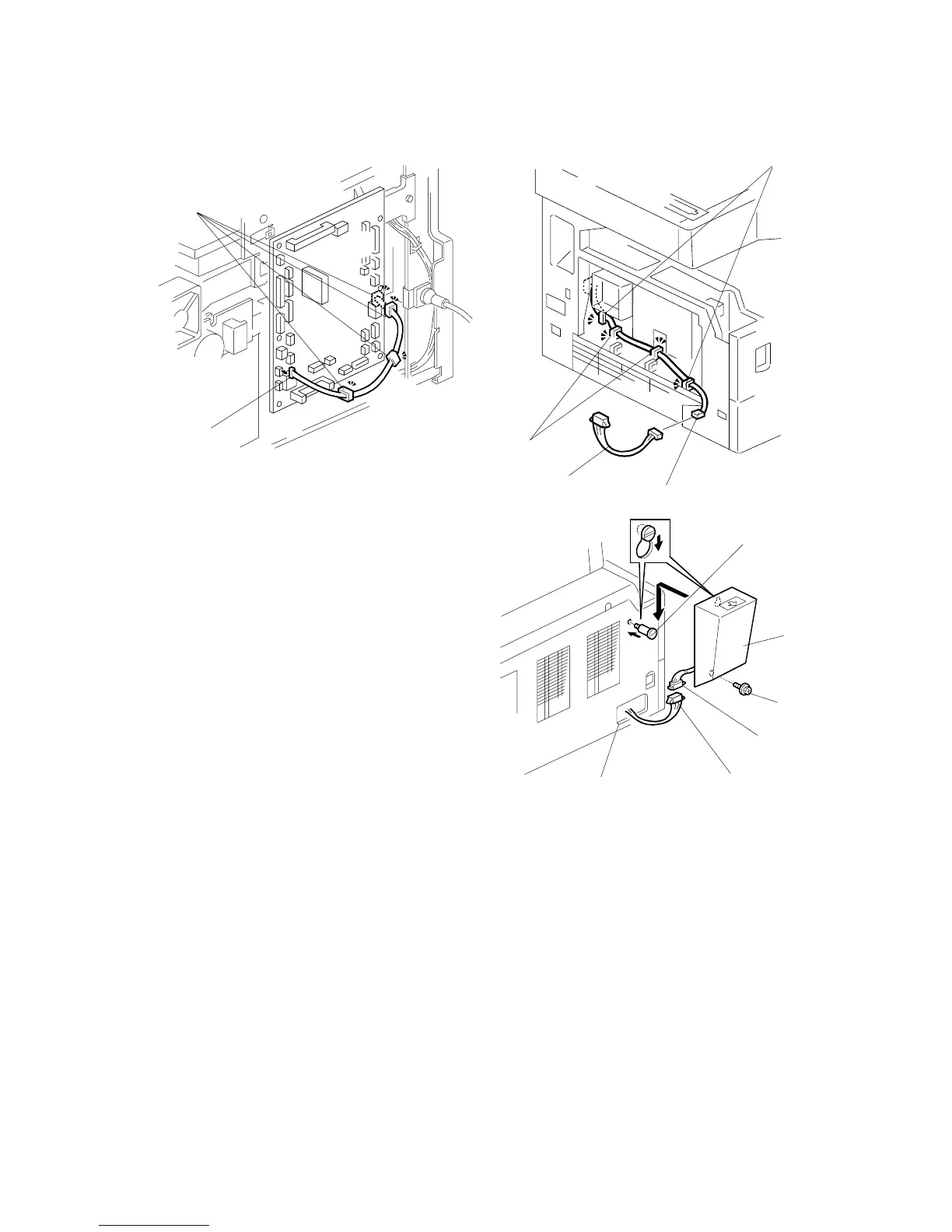
8. Connect the connector [A] to CN126 on
the BICU.
9. Install the clamps [B].
10. Hold the cable with the clamps [B][C][D].
NOTE: The relay cable is not included
in the key counter bracket
accessories.
11. Join the relay cable [E] with the
connector [F].
12. Reinstall the rear cover.
13. Pass the relay cable through the
opening [G] and reinstall the left cover.
14. Install the stepped screw [H].
15. Join the connectors [I][J].
16. Pass the joined connectors through the opening of the key counter holder
assembly [K], and put the connectors inside the assembly.
17. Hook the key counter holder assembly onto the stepped screw [H]. Check that
the cable is not caught between the left cover and the key counter holder
assembly.
18. Secure the key counter holder assembly with the screw [L].
19. Go to SP5-113. Change setting to 11.
20. Enter User Tools. Go to Systems Settings> Key Operator Tools> Extended
Charge Unit Management. Change to 1.
B121I909.WMF
B121I908.WMF
B121I907.WMF
[H]
[K]
[L]
[I]
[J]
[G]
[A]
[C]
[B]
[D]
[E]
[F]