126 Rockwell Automation Publication 193-UM015D-EN-P - February 2015
Chapter 5 Operating Modes
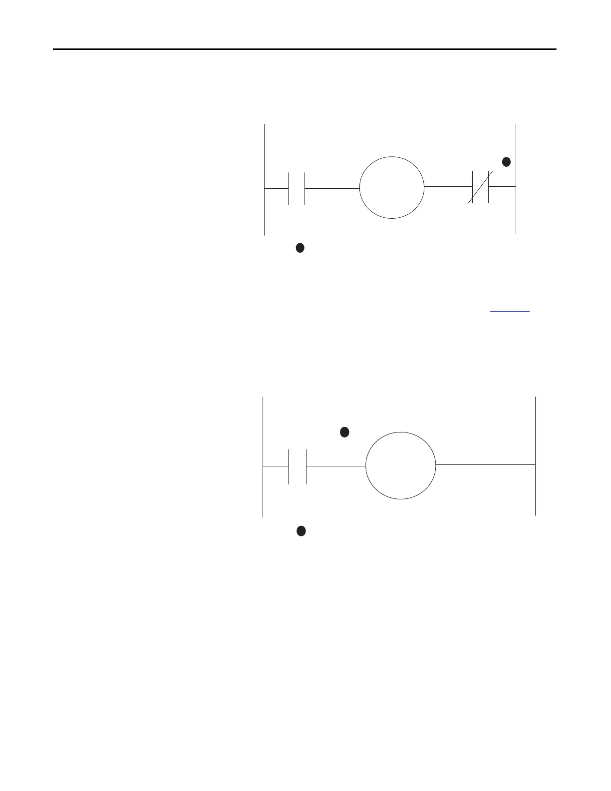
and Relay 1 is configured as a normally open Normal Relay, which receives
commands from an automation controller to energize the contactor coil.
Figure 43 - Trip Relay Wiring Diagram
For Control Module firmware v3.000 and higher, the E300 Electronic Overload
Relay can also be wired as a Control Relay in which the relay that is controlled by
the communications network opens when a trip event is present. Figure 44
is a
wiring diagram of a Non-Reversing Starter with Relay 0 configured as a Control
Relay. Relay 0 receives control commands from an automation controller to
energize or de-energize the contactor coil. Relay 0 also goes to an open state when
there is a trip event.
Figure 44 - Control Relay Wiring Diagram
Relay 1
Relay 0
Configured as a
Trip Relay
R13 R14
A1
A2
M
R03
R04
1
1
Contact shown with supply voltage applied.
Relay 0
Configured as a
Control Relay
R03 R04
A1
A2
M
1
1
Contact shown with supply voltage applied.
 Loading...


