U.2.47
Date Code 20090715 User’s Guide SEL-421 Relay
Installation
Connection
Step 18. Set the relay date and time via the communications ports or
front panel (see Making Simple Settings Changes on
page U.4.13).
Step 19. Follow your company standard procedure to return the relay to
service.
Communications
Ports Connections
The SEL-421 has three rear-panel EIA-232 serial communications ports
labeled PORT 1, PORT 2, and PORT 3 and one front-panel port, PORT F. For
information on serial communications, see Establishing Communication on
page U.4.4, Serial Communication on page R.4.2, and Serial Port Hardware
Protocol on page R.5.1.
In addition, the rear panel features a PORT 5 for an optional communications
card. For additional information about communications topologies and
standard protocols that are available in the SEL-421, see Network Connections
on page U.2.48, Section 6: SEL Communications Processor Applications in
the Applications Handbook, Section 7: Direct Network Communication in the
Applications Handbook, Section 6: DNP3 Communications in the Reference
Manual, and Section 8: IEC 61850 Communications in the Reference Manual.
Serial Ports
The SEL-421 serial communications ports use EIA-232 standard signal levels
in a D-subminiature 9-pin connector. To establish communication between the
relay and a DTE device (a computer terminal, for example) with a
D-subminiature 9-pin connector, use an SEL Cable C234A (see Making an
EIA-232 Serial Port Connection on page U.4.5).
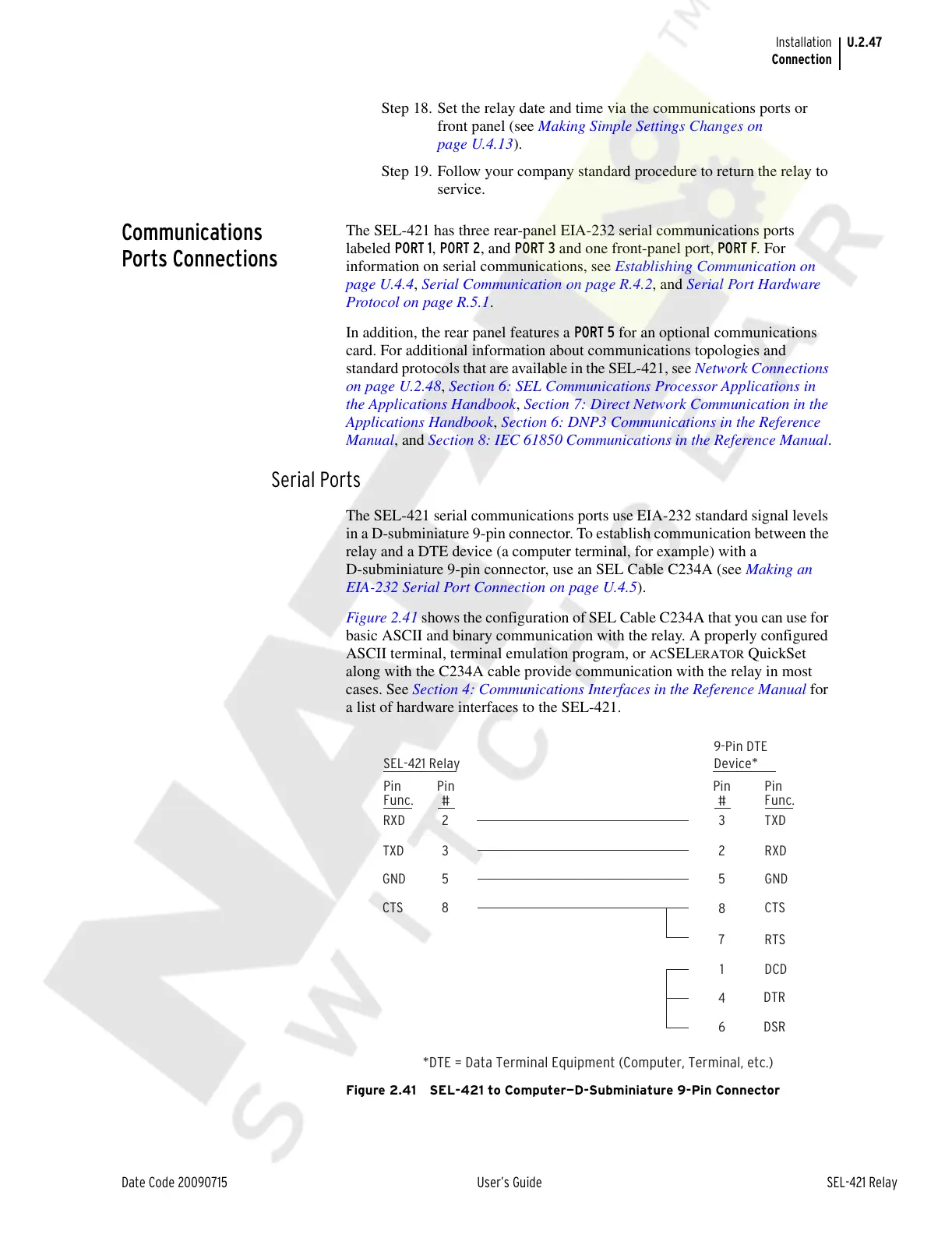
Figure 2.41 shows the configuration of SEL Cable C234A that you can use for
basic ASCII and binary communication with the relay. A properly configured
ASCII terminal, terminal emulation program, or
ACSELERATOR QuickSet
along with the C234A cable provide communication with the relay in most
cases. See Section 4: Communications Interfaces in the Reference Manual for
a list of hardware interfaces to the SEL-421.
Figure 2.41 SEL-421 to Computer—D-Subminiature 9-Pin Connector
*DTE = Data Terminal Equipment (Computer, Terminal, etc.)
SEL-421 Relay
23
3
5
8
2
5
8
7
RXD TXD
TXD RXD
GND GND
CTS CTS
RTS
DCD
DTR
DSR
1
4
6
Pin
Func.
Pin
Func.
Pin
#
Pin
#
9-Pin DTE
Device
*
Courtesy of NationalSwitchgear.com