U.6.20
SEL-421 Relay User’s Guide Date Code 20090715
Testing and Troubleshooting
Test Methods
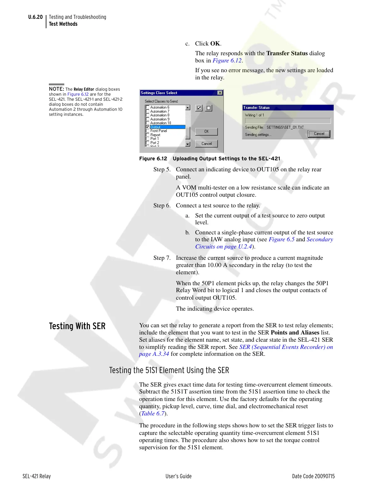
c. Click OK.
The relay responds with the Transfer Status dialog
box in Figure 6.12.
If you see no error message, the new settings are loaded
in the relay.
NOTE: The Relay Editor dialog boxes
shown in Figure 6.12 are for the
SEL-421. The SEL-421-1 and SEL-421-2
dialog boxes do not contain
Automation 2 through Automation 10
setting instances.
Figure 6.12 Uploading Output Settings to the SEL-421
Step 5. Connect an indicating device to OUT105 on the relay rear
panel.
A VOM multi-tester on a low resistance scale can indicate an
OUT105 control output closure.
Step 6. Connect a test source to the relay.
a. Set the current output of a test source to zero output
level.
b. Connect a single-phase current output of the test source
to the IAW analog input (see Figure 6.5 and Secondary
Circuits on page U.2.4).
Step 7. Increase the current source to produce a current magnitude
greater than 10.00 A secondary in the relay (to test the
element).
When the 50P1 element picks up, the relay changes the 50P1
Relay Word bit to logical 1 and closes the output contacts of
control output OUT105.
The indicating device operates.
Testing With SER
You can set the relay to generate a report from the SER to test relay elements;
include the element that you want to test in the SER Points and Aliases list.
Set aliases for the element name, set state, and clear state in the SEL-421 SER
to simplify reading the SER report. See SER (Sequential Events Recorder) on
page A.3.34 for complete information on the SER.
Testing the 51S1 Element Using the SER
The SER gives exact time data for testing time-overcurrent element timeouts.
Subtract the 51S1T assertion time from the 51S1 assertion time to check the
operation time for this element. Use the factory defaults for the operating
quantity, pickup level, curve, time dial, and electromechanical reset
(Tabl e 6 . 7 ).
The procedure in the following steps shows how to set the SER trigger lists to
capture the selectable operating quantity time-overcurrent element 51S1
operating times. The procedure also shows how to set the torque control
supervision for the 51S1 element.
Courtesy of NationalSwitchgear.com