U.2.35
Date Code 20090715 User’s Guide SEL-421 Relay
Installation
Connection
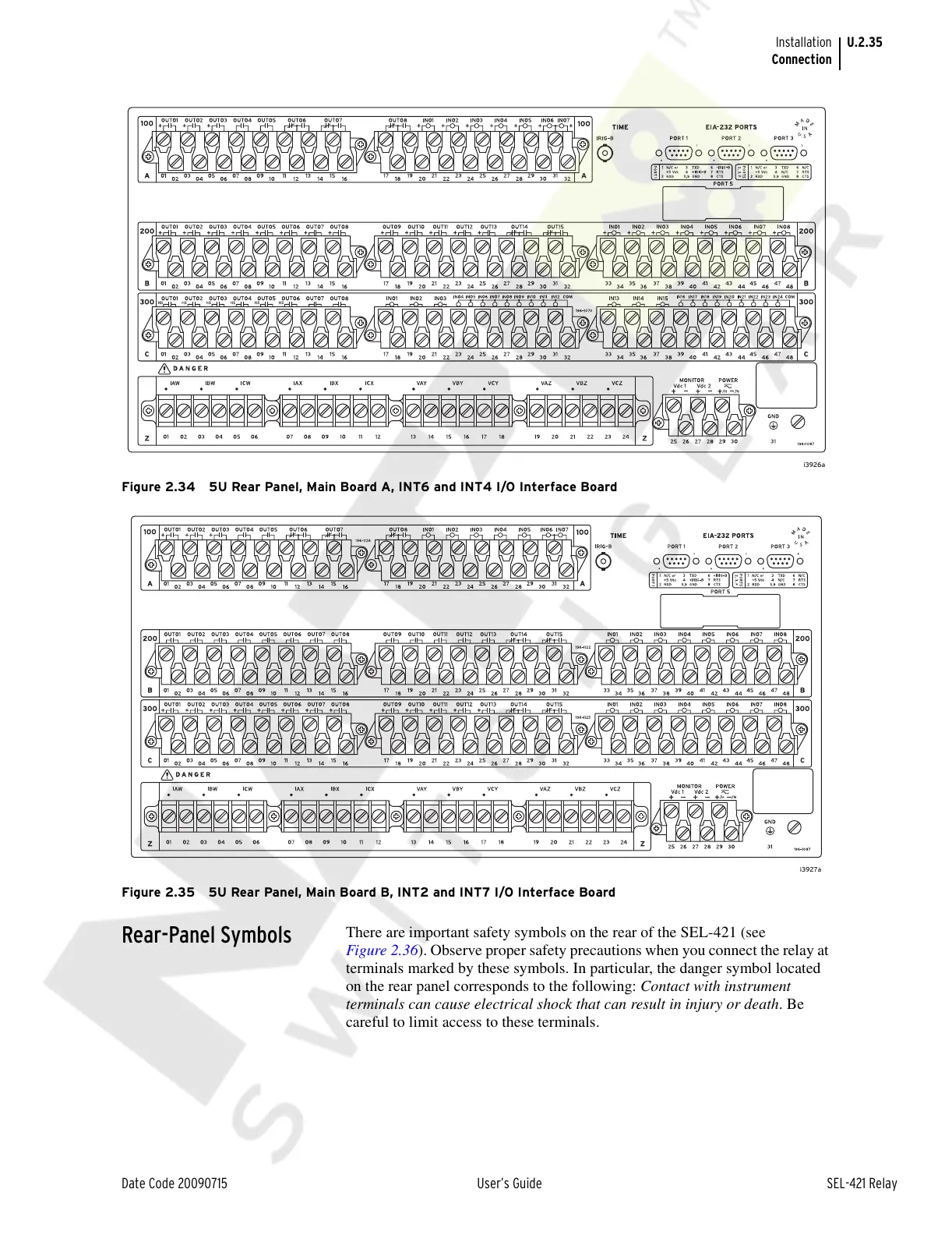
Figure 2.34 5U Rear Panel, Main Board A, INT6 and INT4 I/O Interface Board
Figure 2.35 5U Rear Panel, Main Board B, INT2 and INT7 I/O Interface Board
Rear-Panel Symbols
There are important safety symbols on the rear of the SEL-421 (see
Figure 2.36). Observe proper safety precautions when you connect the relay at
terminals marked by these symbols. In particular, the danger symbol located
on the rear panel corresponds to the following: Contact with instrument
terminals can cause electrical shock that can result in injury or death. Be
careful to limit access to these terminals.
Courtesy of NationalSwitchgear.com