U.5.41
Date Code 20090715 User’s Guide SEL-421 Relay
Front-Panel Operations
Front-Panel Operator Control Pushbuttons
Press the operator control pushbuttons momentarily to toggle on and off the
functions listed adjacent to each LED/pushbutton combination. The CLOSE and
TRIP pushbuttons momentarily assert the close and trip relay outputs after a
short delay.
The operator control pushbuttons and LEDs are programmable. Figure 5.45
describes the factory defaults for the operator controls.
There are two ways to program the operator control pushbuttons. The first is
through front-panel settings PBn_HMI. These settings allow any of the
operator control pushbuttons to be programmed to display a particular HMI
screen category. The HMI screen categories available are Alarm Points,
Display Points, and Event Summaries, and SER. Front-panel setting
NUM_ER allows the user to define the number of event summaries that are
displayed via the operator control pushbutton; it has no effect on the event
summaries automatically displayed or the event summaries available through
the main menu. Each HMI screen category can be assigned to a single
pushbutton. Attempting to program more than one pushbutton to a single HMI
screen category will result in an error. After assigning a pushbutton to an HMI
screen category, pressing the pushbutton will jump to the first available HMI
screen in that particular category. If more than one screen is available, a
navigation scroll bar will be displayed. Pressing the navigation arrows will
scroll through the available screens. Subsequent pressing of the operator
control pushbutton will advance through the available screens, behaving the
same as the {Right Arrow} or the {Down Arrow} pushbutton. Pressing the {ESC}
pushbutton will return the user to the
ROTATING DISPLAY. The second way to
program the operator control pushbutton is through SEL
OGIC control
equations, using the pushbutton output as a programming element.
Using SEL
OGIC control equations, you can readily change the default LED
functions. Use the slide-in labels to mark the pushbuttons and pushbutton
LEDs with custom names to reflect any programming changes that you make.
The labels are keyed; you can insert each Operator Control Label in only one
position on the front of the relay. Included on the SEL-421 Relay Product
Literature CD are word processor templates for printing slide-in labels. See
the instructions included in the Configurable Label kit for more information
on changing the slide-in labels.
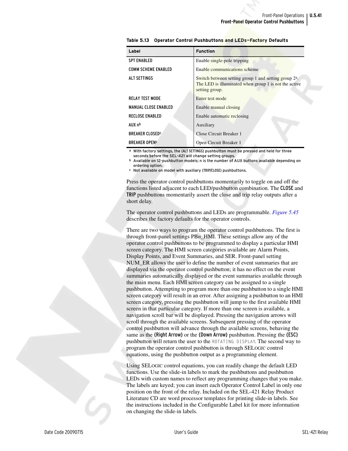
Table 5.13 Operator Control Pushbuttons and LEDs—Factory Defaults
Label Function
SPT ENABLED Enable single-pole tripping
COMM SCHEME ENABLED Enable communications scheme
ALT SETTINGS Switch between setting group 1 and setting group 2
a
.
The LED is illuminated when group 1 is not the active
setting group.
a
With factory settings, the {ALT SETTINGS} pushbutton must be pressed and held for three
seconds before the SEL-421 will change setting groups.
RELAY TEST MODE Enter test mode
MANUAL CLOSE ENABLED Enable manual closing
RECLOSE ENABLED Enable automatic reclosing
AUX n
b
b
Available on 12-pushbutton models; n is the number of AUX buttons available depending on
ordering option.
Auxiliary
BREAKER CLOSED
c
c
Not available on model with auxiliary {TRIP/CLOSE} pushbuttons.
Close Circuit Breaker 1
BREAKER OPEN
c
Open Circuit Breaker 1
Courtesy of NationalSwitchgear.com