U.4.76
SEL-421 Relay User’s Guide Date Code 20090715
Basic Relay Operations
Configuring High-Accuracy Timekeeping
The IRIG Time Mark Period value indicates the instantaneous period in which
the relay measures the time-source inputs. The relay displays the time mark
periods showing the present time precision derived from the applied
time-source signals.
The TIME Q command is also helpful for troubleshooting IRIG problems. If
the IRIG Time Mark Period value changes significantly between successive
TIME Q commands, there may be too much noise in the signal for the relay
timekeeping function.
Adaptive Internal Clock Period Adjustment
The Internal Clock Period is the internal relay timekeeping period. The relay
adjusts this master internal clock when you apply HIRIG mode timekeeping,
adapting the internal relay clock for your installation temperature conditions.
If you lose the HIRIG timing lock, the relay internal clock operates at this
precisely adapted clock period until HIRIG mode is restored. Time tags for
event reports during a loss of HIRIG mode timekeeping remain very accurate.
Lower accuracy time sources do not adaptively adjust the internal relay clock
period.
Monitoring
High-Accuracy Time
Source Status
The purpose of the procedure in the following steps is to show one method for
deriving the TIME Q Time Source information from Relay Word bits TSOK
and TIRIG. The TSOK Relay Word bit is at logical 1 when the relay is in
HIRIG time mode. For this application example, use a PSV (Protection
SEL
OGIC Variable) to monitor time keeping status.
PSV01 asserts when the relay is synchronized to the HIRIG source. A
departure from this condition asserts the relay alarm output (OUT108 for this
application example).
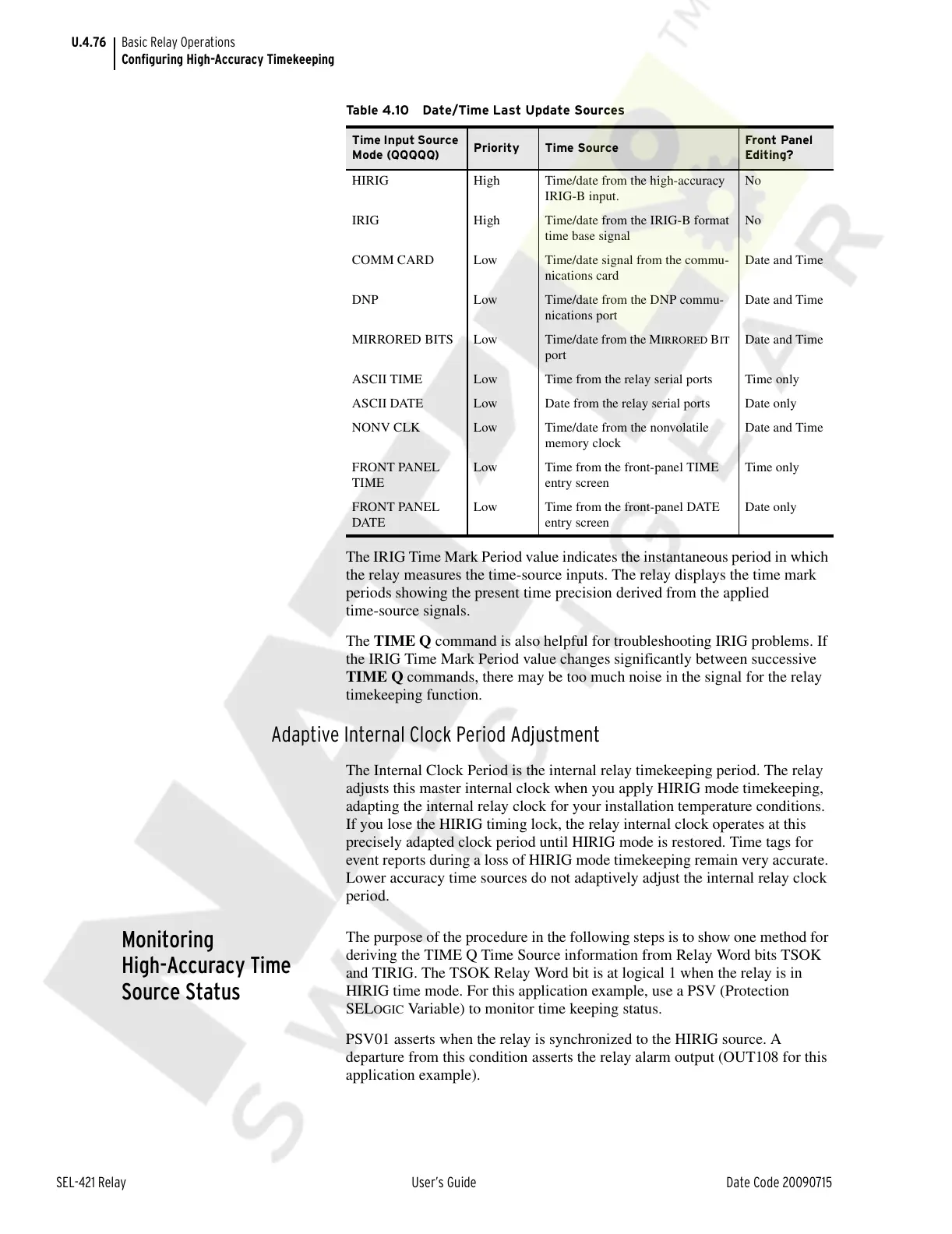
Table 4.10 Date/Time Last Update Sources
Time Input Source
Mode (QQQQQ)
Priority Time Source
Front Panel
Editing?
HIRIG High Time/date from the high-accuracy
IRIG-B input.
No
IRIG High Time/date from the IRIG-B format
time base signal
No
COMM CARD Low Time/date signal from the commu-
nications card
Date and Time
DNP Low Time/date from the DNP commu-
nications port
Date and Time
MIRRORED BITS Low Time/date from the M
IRRORED BIT
port
Date and Time
ASCII TIME Low Time from the relay serial ports Time only
ASCII DATE Low Date from the relay serial ports Date only
NONV CLK Low Time/date from the nonvolatile
memory clock
Date and Time
FRONT PANEL
TIME
Low Time from the front-panel TIME
entry screen
Time only
FRONT PANEL
DATE
Low Time from the front-panel DATE
entry screen
Date only
Courtesy of NationalSwitchgear.com