U.2.29
Date Code 20090715 User’s Guide SEL-421 Relay
Installation
Jumpers
Step 13. Replace any cables previously removed from serial ports.
Step 14. Follow your company standard procedure to return the relay to
service.
Step 15. At relay power-up, confirm that the relay does not display a
status warning about I/O board addresses. For information on
this status warning, see Relay Self-Tests on page U.6.38.
Auxiliary {TRIP}/
{CLOSE} Pushbutton
and Breaker Status
LED Jumpers (select
models only)
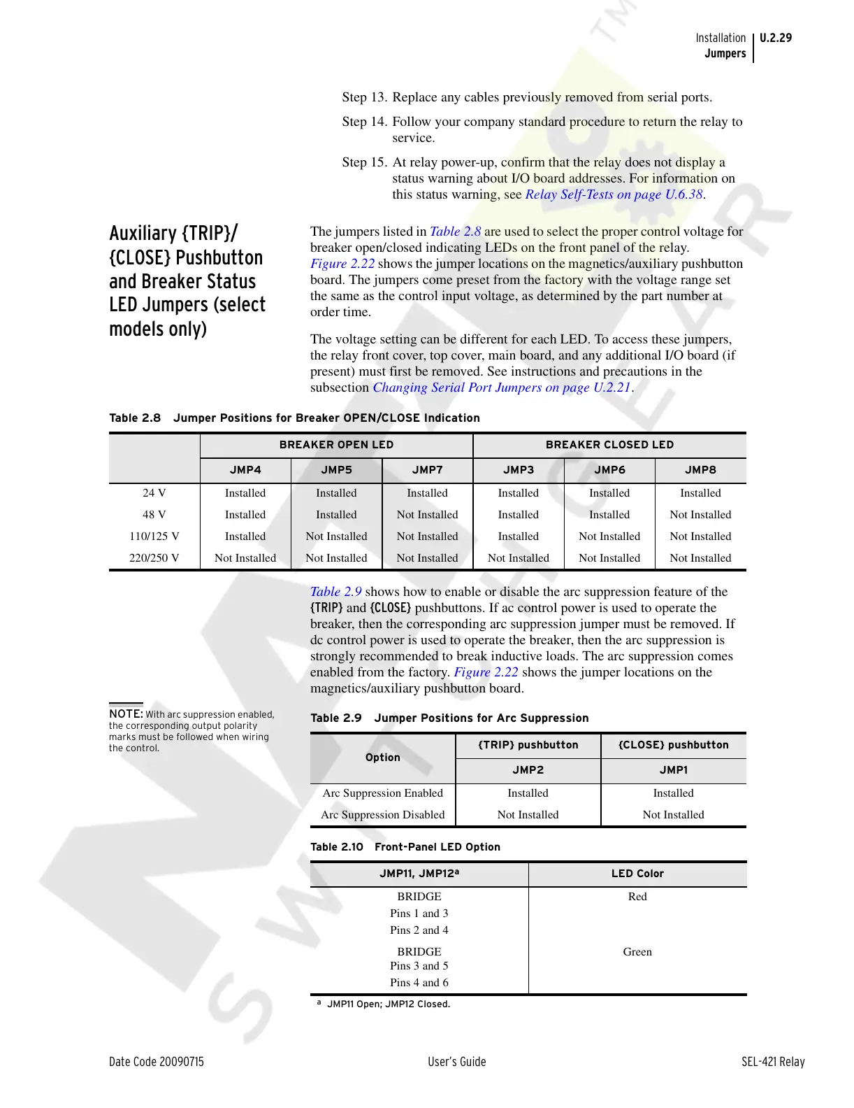
The jumpers listed in Table 2.8 are used to select the proper control voltage for
breaker open/closed indicating LEDs on the front panel of the relay.
Figure 2.22 shows the jumper locations on the magnetics/auxiliary pushbutton
board. The jumpers come preset from the factory with the voltage range set
the same as the control input voltage, as determined by the part number at
order time.
The voltage setting can be different for each LED. To access these jumpers,
the relay front cover, top cover, main board, and any additional I/O board (if
present) must first be removed. See instructions and precautions in the
subsection Changing Serial Port Jumpers on page U.2.21.
Table 2.9 shows how to enable or disable the arc suppression feature of the
{TRIP} and {CLOSE} pushbuttons. If ac control power is used to operate the
breaker, then the corresponding arc suppression jumper must be removed. If
dc control power is used to operate the breaker, then the arc suppression is
strongly recommended to break inductive loads. The arc suppression comes
enabled from the factory. Figure 2.22 shows the jumper locations on the
magnetics/auxiliary pushbutton board.
NOTE: With arc suppression enabled,
the corresponding output polarity
marks must be followed when wiring
the control.
Table 2.8 Jumper Positions for Breaker OPEN/CLOSE Indication
BREAKER OPEN LED BREAKER CLOSED LED
JMP4 JMP5 JMP7 JMP3 JMP6 JMP8
24 V Installed Installed Installed Installed Installed Installed
48 V Installed Installed Not Installed Installed Installed Not Installed
110/125 V Installed Not Installed Not Installed Installed Not Installed Not Installed
220/250 V Not Installed Not Installed Not Installed Not Installed Not Installed Not Installed
Ta b l e 2 .9 J u m p e r P o s i t i ons for Arc Suppression
Option
{TRIP} pushbutton {CLOSE} pushbutton
JMP2 JMP1
Arc Suppression Enabled Installed Installed
Arc Suppression Disabled Not Installed Not Installed
Tab l e 2 .1 0 Fro n t -Pa n el L ED O p ti o n
JMP11, JMP12
a
a
JMP11 Open; JMP12 Closed.
LED Color
BRIDGE
Pins 1 and 3
Pins 2 and 4
Red
BRIDGE
Pins 3 and 5
Pins 4 and 6
Green
Courtesy of NationalSwitchgear.com