U.6.23
Date Code 20090715 User’s Guide SEL-421 Relay
Testing and Troubleshooting
Test Methods
e. Type GROUND O/C 1 LINE 1 in the Alias Name
field.
f. Type 51S1 TIMEOUT in the Set Alias field.
g. Type 51S1 DROPOUT in the Clear Alias field.
h. Click on the OK button.
i. Repeat Steps Step a–Step h for SITM2 SER Points
and Aliases, Point 2, with setting values 51S1,
GROUND O/C 1 LINE 1, 51S1 PICKED UP, 51S1
RESET. Figure 6.14 shows the entry field for SITM2
just before pressing the OK button.
You can enter as many as 250 relay elements in the SER Points
and Aliases list (see SER (Sequential Events Recorder) on
page A.3.34).
Step 5. Click File > Save to save the new settings in
ACSELERATOR
QuickSet.
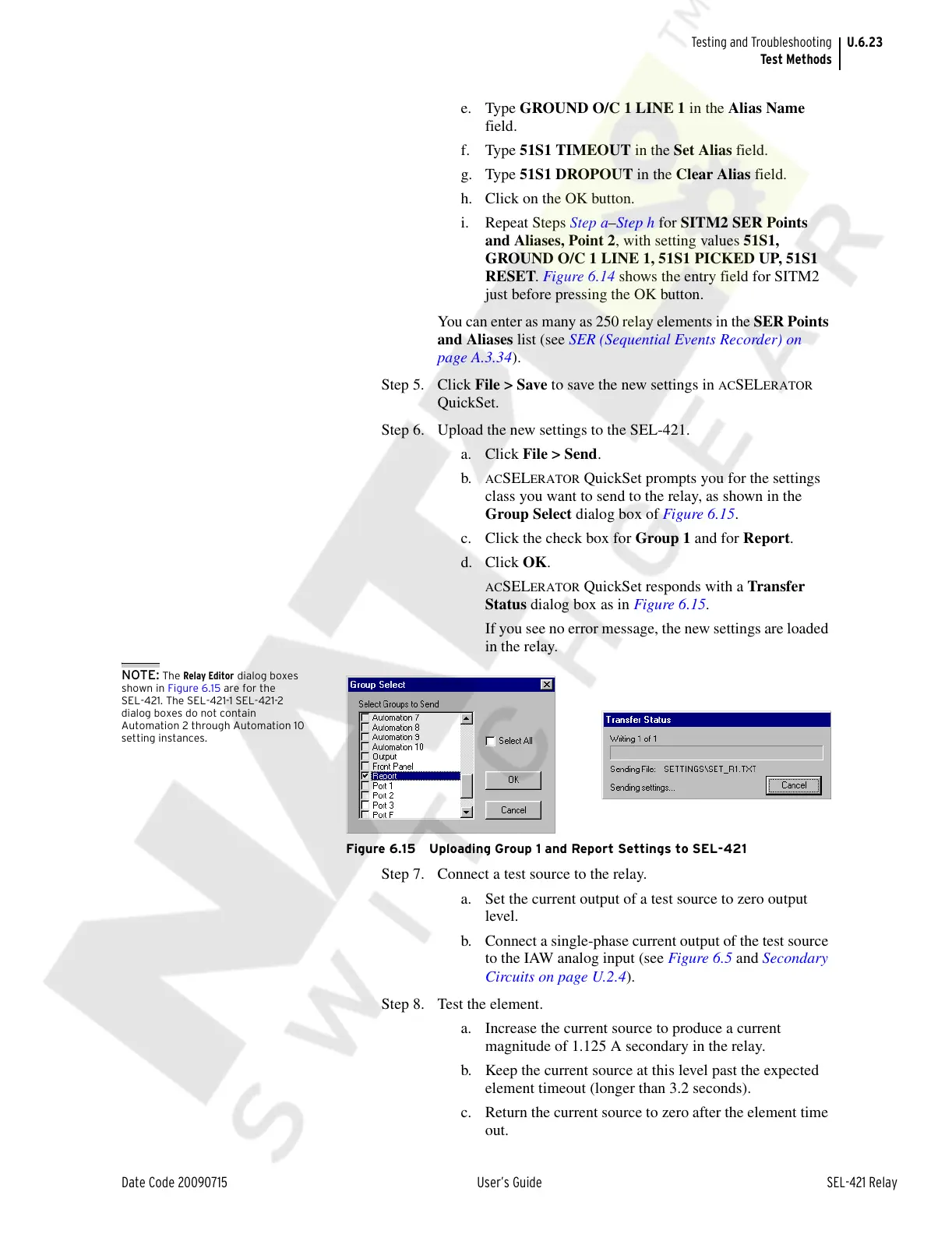
Step 6. Upload the new settings to the SEL-421.
a. Click File > Send.
b.
ACSELERATOR QuickSet prompts you for the settings
class you want to send to the relay, as shown in the
Group Select dialog box of Figure 6.15.
c. Click the check box for Group 1 and for Report.
d. Click OK.
ACSELERATOR QuickSet responds with a Transfer
Status dialog box as in Figure 6.15.
If you see no error message, the new settings are loaded
in the relay.
NOTE: The Relay Editor dialog boxes
shown in Figure 6.15 are for the
SEL-421. The SEL-421-1 SEL-421-2
dialog boxes do not contain
Automation 2 through Automation 10
setting instances.
Figure 6.15 Uploading Group 1 and Report Settings to SEL-421
Step 7. Connect a test source to the relay.
a. Set the current output of a test source to zero output
level.
b. Connect a single-phase current output of the test source
to the IAW analog input (see Figure 6.5 and Secondary
Circuits on page U.2.4).
Step 8. Test the element.
a. Increase the current source to produce a current
magnitude of 1.125 A secondary in the relay.
b. Keep the current source at this level past the expected
element timeout (longer than 3.2 seconds).
c. Return the current source to zero after the element time
out.
Courtesy of NationalSwitchgear.com