U.4.65
Date Code 20090715 User’s Guide SEL-421 Relay
Basic Relay Operations
Operating the Relay Inputs and Outputs
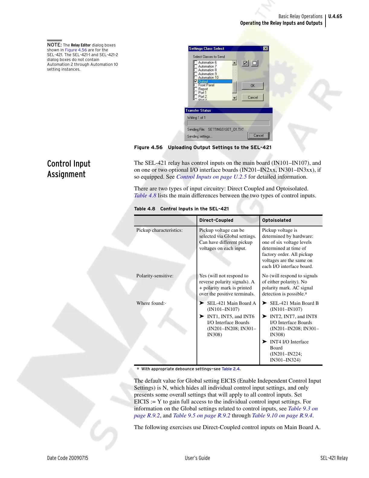
NOTE: The Relay Editor dialog boxes
shown in Figure 4.56 are for the
SEL-421. The SEL-421-1 and SEL-421-2
dialog boxes do not contain
Automation 2 through Automation 10
setting instances.
Figure 4.56 Uploading Output Settings to the SEL-421
Control Input
Assignment
The SEL-421 relay has control inputs on the main board (IN101–IN107), and
on one or two optional I/O interface boards (IN201–IN2xx, IN301–IN3xx), if
so equipped. See Control Inputs on page U.2.5 for detailed information.
There are two types of input circuitry: Direct Coupled and Optoisolated.
Table 4.8 lists the main differences between the two types of control inputs.
The default value for Global setting EICIS (Enable Independent Control Input
Settings) is N, which hides all individual control input settings, and only
presents some overall settings that will apply to all control inputs. Set
EICIS := Y to gain full access to the individual control input settings. For
information on the Global settings related to control inputs, see Table 9.3 on
page R.9.2, and Table 9.5 on page R.9.2 through Table 9.10 on page R.9.4.
The following exercises use Direct-Coupled control inputs on Main Board A.
Table 4.8 Control Inputs in the SEL-421
Direct-Coupled Optoisolated
Pickup characteristics: Pickup voltage can be
selected via Global settings.
Can have different pickup
voltages on each input.
Pickup voltage is
determined by hardware:
one of six voltage levels
determined at time of
factory order. All pickup
voltages are the same on
each I/O interface board.
Polarity-sensitive: Yes (will not respond to
reverse polarity signals). A
+ polarity mark is printed
over the positive terminals.
No (will respond to signals
of either polarity). No
polarity mark. AC signal
detection is possible.
a
a
With appropriate debounce settings—see Ta b le 2 .4 .
Where found:· ➤ SEL-421 Main Board A
(IN101–IN107)
➤ INT1, INT5, and INT6
I/O Interface Boards
(IN201–IN208; IN301–
IN308)
➤ SEL-421 Main Board B
(IN101–IN107)
➤ INT2, INT7, and INT8
I/O Interface Boards
(IN201–IN208; IN301–
IN308)
➤ INT4 I/O Interface
Board
(IN201–IN224;
IN301–IN324)
Courtesy of NationalSwitchgear.com