U.5.40
SEL-421 Relay User’s Guide Date Code 20090715
Front-Panel Operations
Front-Panel Operator Control Pushbuttons
The OSB LED illuminates when the relay detects an out-of-step condition
(Relay Word bit OSB is asserted). See Out-of-Step Logic on page R.1.43 for
complete details.
The LOP LED illuminates when the relay detects a loss-of-potential condition
(Relay Word bit LOP is asserted). See Loss-of-Potential Logic on page R.1.23
for complete details.
Synchrophasor
Status
The PMCU OK target LED illuminates when the relay is enabled for
synchrophasor measurement (Relay Word bits TSOK and PMDOK are
asserted). See Synchrophasor Relay Word Bits on page R.7.19 for complete
details.
The IRIG LOCKED target LED illuminates when the relay detects
synchronization to an external clock with less than 500 ns of jitter (Relay
Word bit TIRIG is asserted). See IRIG-B on page U.4.71 for complete details.
Front-Panel Operator Control Pushbuttons
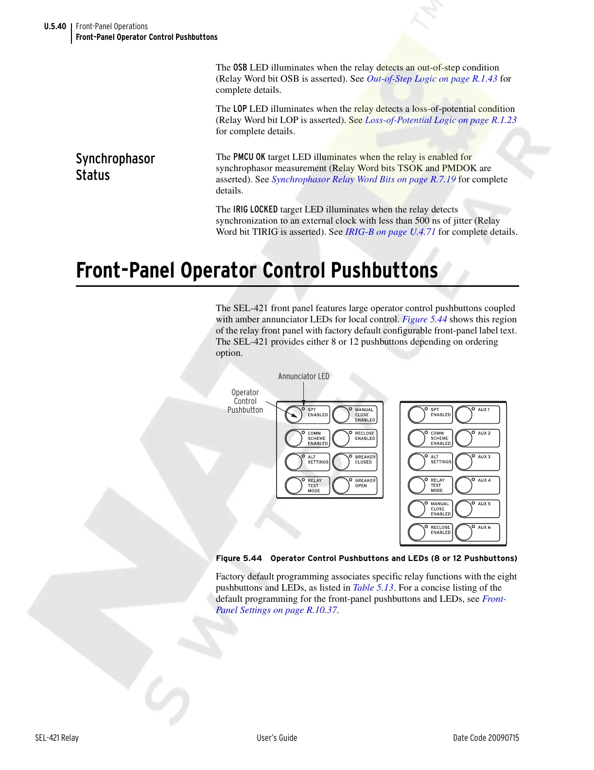
The SEL-421 front panel features large operator control pushbuttons coupled
with amber annunciator LEDs for local control. Figure 5.44 shows this region
of the relay front panel with factory default configurable front-panel label text.
The SEL-421 provides either 8 or 12 pushbuttons depending on ordering
option.
Figure 5.44 Operator Control Pushbuttons and LEDs (8 or 12 Pushbuttons)
Factory default programming associates specific relay functions with the eight
pushbuttons and LEDs, as listed in Table 5.13. For a concise listing of the
default programming for the front-panel pushbuttons and LEDs, see Front-
Panel Settings on page R.10.37.
Operator
Control
Pushbutton
Annunciator LED
Courtesy of NationalSwitchgear.com