U.2.12
SEL-421 Relay User’s Guide Date Code 20090715
Installation
Plug-In Boards
If the relay does not maintain the date and time after power loss, replace the
battery (see Replacing the Lithium Battery on page U.2.46).
Communications
Interfaces
The SEL-421 has several communications interfaces you can use to
communicate with other IEDs (intelligent electronic devices) via EIA-232
ports: PORT 1, PORT 2, PORT 3, and PORT F. See Section 4: Communications
Interfaces in the Reference Manual for more information and options for
connecting your relay to the communications interfaces.
An optional communications card provides Ethernet capability for the
SEL-421. A communications card gives the relay access to popular Ethernet
networking standards including TCP/IP, FTP, Telnet, DNP3, and IEC 61850
over local area and wide area networks. The Ethernet card with IEC 61850
support is only available at purchase as a factory-installed option. For
information on DNP3 applications, see Section 6: DNP3 Communications in
the Reference Manual. For more information on IEC 61850 applications, see
Section 8: IEC 61850 Communications in the Reference Manual.
Other Shared
Configuration
Attributes
All versions of the SEL-421 also feature ground, power, and battery monitor
connections. See Connection on page U.2.31 for information on these relay
interface features.
Plug-In Boards
The SEL-421 is available in many input/output configuration options. The
relay base model is a 3U chassis with Main Board A or Main Board B I/O and
screw terminal connector connections (see Figure 2.2). Other ordering options
include versions of the relay in larger enclosures (4U or 5U) with all, partial,
or no extra I/O boards installed.
Plug-in communications cards are also available for the SEL-421. The
optional Ethernet card allows you to use TCP/IP, FTP, Telnet, DNP3 LAN/
WAN, and IEC 61850 applications on an Ethernet network. This card is only
available at the time of purchase of a new SEL-421 as a factory-installed
option or as a factory-installed conversion to an existing relay.
I/O Interface Boards
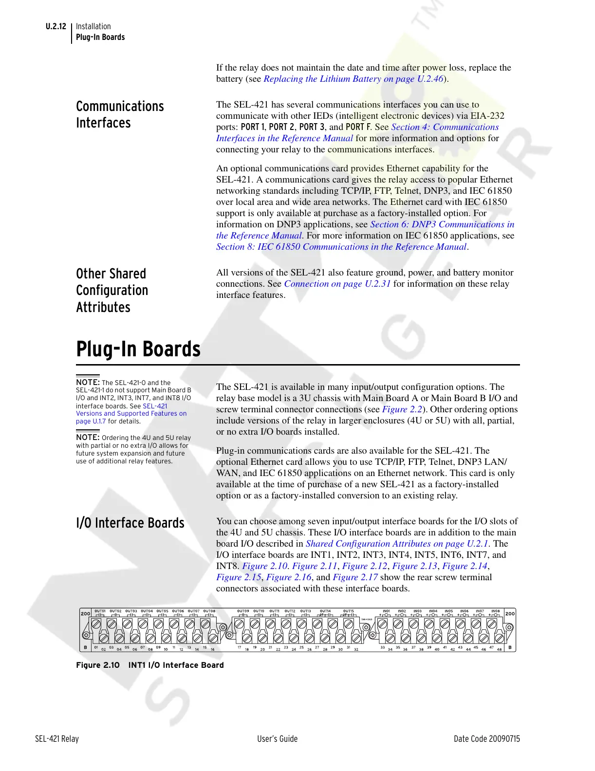
You can choose among seven input/output interface boards for the I/O slots of
the 4U and 5U chassis. These I/O interface boards are in addition to the main
board I/O described in Shared Configuration Attributes on page U.2.1. The
I/O interface boards are INT1, INT2, INT3, INT4, INT5, INT6, INT7, and
INT8. Figure 2.10. Figure 2.11, Figure 2.12, Figure 2.13, Figure 2.14,
Figure 2.15, Figure 2.16, and Figure 2.17 show the rear screw terminal
connectors associated with these interface boards.
Figure 2.10 INT1 I/O Interface Board
NOTE: The SEL-421-0 and the
SEL-421-1 do not support Main Board B
I/O and INT2, INT3, INT7, and INT8 I/O
interface boards. See SEL-421
Versions and Supported Features on
page U.1.7 for details.
NOTE: Ordering the 4U and 5U relay
with partial or no extra I/O allows for
future system expansion and future
use of additional relay features.
Courtesy of NationalSwitchgear.com