U.6.7
Date Code 20090715 User’s Guide SEL-421 Relay
Testing and Troubleshooting
Testing Features and Tools
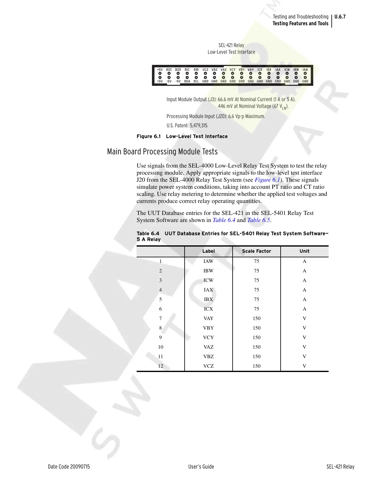
Figure 6.1 Low-Level Test Interface
Main Board Processing Module Tests
Use signals from the SEL-4000 Low-Level Relay Test System to test the relay
processing module. Apply appropriate signals to the low-level test interface
J20 from the SEL-4000 Relay Test System (see Figure 6.1). These signals
simulate power system conditions, taking into account PT ratio and CT ratio
scaling. Use relay metering to determine whether the applied test voltages and
currents produce correct relay operating quantities.
The UUT Database entries for the SEL-421 in the SEL-5401 Relay Test
System Software are shown in Tab le 6.4 and Table 6.5.
U.S. Patent 5,479,315.
Input Module Output (J3): 66.6 mV At Nominal Current (1 A or 5 A).
SEL-421 Relay
Low-Level Test Interface
446 mV at Nominal Voltage (67 V
LN
).
Processing Module Input (J20): 6.6 Vp-p Maximum.
Table 6.4 UUT Database Entries for SEL-5401 Relay Test System Software—
5ARelay
Label Scale Factor Unit
1IAW75 A
2IBW75 A
3ICW75 A
4IAX75 A
5IBX75 A
6ICX75 A
7VAY150V
8VBY150 V
9VCY150 V
10 VAZ 150 V
11 VBZ 150 V
12 VCZ 150 V
Courtesy of NationalSwitchgear.com