U.5.38
SEL-421 Relay User’s Guide Date Code 20090715
Front-Panel Operations
Operation and Target LEDs
The TAR R command and the {TARGET RESET} pushbutton also control the
TRGTR Relay Word bit, which can be used for other functions, as shown in
Figure 1.81 on page R.1.125. TRGTR is the factory default setting for the
unlatch trip SEL
OGIC control equation, ULTR, in group settings. See
Table 1.72 on page R.1.108.
You can reset the targets from the
ACSELERATOR QuickSet Control branch of
the HMI tree view. Programming specific conditions in the SEL
OGIC control
equation RSTTRGT is another method to reset the relay targets. Access
RSTTRGT in the relay Global settings (Data Reset Control); to use
RSTTRGT, you must enable data reset control with global setting
EDRSTC := Y.
Trip Type
The SEL-421 indicates essential information about the most recent relay trip
event with the LEDs of the Trip Type area. These trip types are INST, TIME,
COMM, and SOTF. For information on setting the corresponding trip logic, see
Trip Logic on page R.1.105.
The INST target LED illuminates, indicating operation of the SEL-421
instantaneous elements. This LED lights if elements M1P (the Zone 1 mho
phase distance element) or Z1G (the Zone 1 mho ground distance element)
pick up and the relay has not illuminated the COMM or SOTF targets.
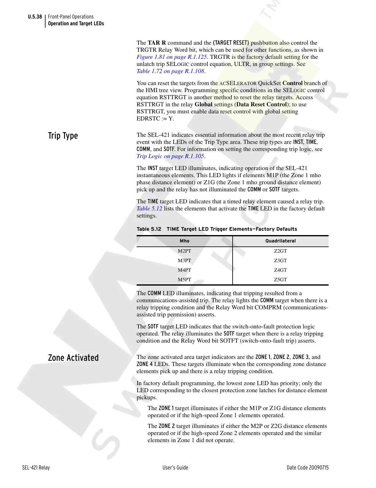
The TIME target LED indicates that a timed relay element caused a relay trip.
Table 5.12 lists the elements that activate the TIME LED in the factory default
settings.
The COMM LED illuminates, indicating that tripping resulted from a
communications-assisted trip. The relay lights the COMM target when there is a
relay tripping condition and the Relay Word bit COMPRM (communications-
assisted trip permission) asserts.
The SOTF target LED indicates that the switch-onto-fault protection logic
operated. The relay illuminates the SOTF target when there is a relay tripping
condition and the Relay Word bit SOTFT (switch-onto-fault trip) asserts.
Zone Activated
The zone activated area target indicators are the ZONE 1, ZONE 2, ZONE 3, and
ZONE 4 LEDs. These targets illuminate when the corresponding zone distance
elements pick up and there is a relay tripping condition.
In factory default programming, the lowest zone LED has priority; only the
LED corresponding to the closest protection zone latches for distance element
pickups.
The ZONE 1 target illuminates if either the M1P or Z1G distance elements
operated or if the high-speed Zone 1 elements operated.
The ZONE 2 target illuminates if either the M2P or Z2G distance elements
operated or if the high-speed Zone 2 elements operated and the similar
elements in Zone 1 did not operate.
Table 5.12 TIME Target LED Trigger Elements—Factory Defaults
Mho Quadrilateral
M2PT Z2GT
M3PT Z3GT
M4PT Z4GT
M5PT Z5GT
Courtesy of NationalSwitchgear.com