U.6.18
SEL-421 Relay User’s Guide Date Code 20090715
Testing and Troubleshooting
Test Methods
Step 4. Upload the new settings to the SEL-421.
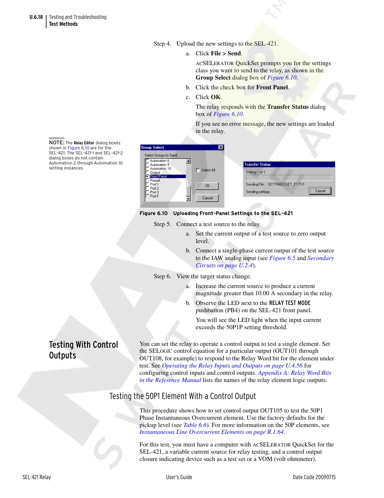
a. Click File > Send.
ACSELERATOR QuickSet prompts you for the settings
class you want to send to the relay, as shown in the
Group Select dialog box of Figure 6.10.
b. Click the check box for Front Panel.
c. Click OK.
The relay responds with the Transfer Status dialog
box of Figure 6.10.
If you see no error message, the new settings are loaded
in the relay.
NOTE: The Relay Editor dialog boxes
shown in Figure 6.10 are for the
SEL-421. The SEL-421-1 and SEL-421-2
dialog boxes do not contain
Automation 2 through Automation 10
setting instances.
Figure 6.10 Uploading Front-Panel Settings to the SEL-421
Step 5. Connect a test source to the relay.
a. Set the current output of a test source to zero output
level.
b. Connect a single-phase current output of the test source
to the IAW analog input (see Figure 6.5 and Secondary
Circuits on page U.2.4).
Step 6. View the target status change.
a. Increase the current source to produce a current
magnitude greater than 10.00 A secondary in the relay.
b. Observe the LED next to the RELAY TEST MODE
pushbutton (PB4) on the SEL-421 front panel.
You will see the LED light when the input current
exceeds the 50P1P setting threshold.
Testing With Control
Outputs
You can set the relay to operate a control output to test a single element. Set
the SEL
OGIC control equation for a particular output (OUT101 through
OUT108, for example) to respond to the Relay Word bit for the element under
test. See Operating the Relay Inputs and Outputs on page U.4.56 for
configuring control inputs and control outputs. Appendix A: Relay Word Bits
in the Reference Manual lists the names of the relay element logic outputs.
Testing the 50P1 Element With a Control Output
This procedure shows how to set control output OUT105 to test the 50P1
Phase Instantaneous Overcurrent element. Use the factory defaults for the
pickup level (see Table 6.6). For more information on the 50P elements, see
Instantaneous Line Overcurrent Elements on page R.1.64.
For this test, you must have a computer with
ACSELERATOR QuickSet for the
SEL-421, a variable current source for relay testing, and a control output
closure indicating device such as a test set or a VOM (volt ohmmeter).
Courtesy of NationalSwitchgear.com