U.6.19
Date Code 20090715 User’s Guide SEL-421 Relay
Testing and Troubleshooting
Test Methods
In this example, use ACSELERATOR QuickSet to configure the relay. You must
have a computer that is communicating with the SEL-421 and running
ACSELERATOR QuickSet (see Making Settings Changes: Initial Global
Settings on page U.4.17).
Step 1. Prepare to control the relay with
ACSELERATOR QuickSet by
establishing communication, checking passwords, and reading
relay settings (see Making Settings Changes: Initial Global
Settings on page U.4.17).
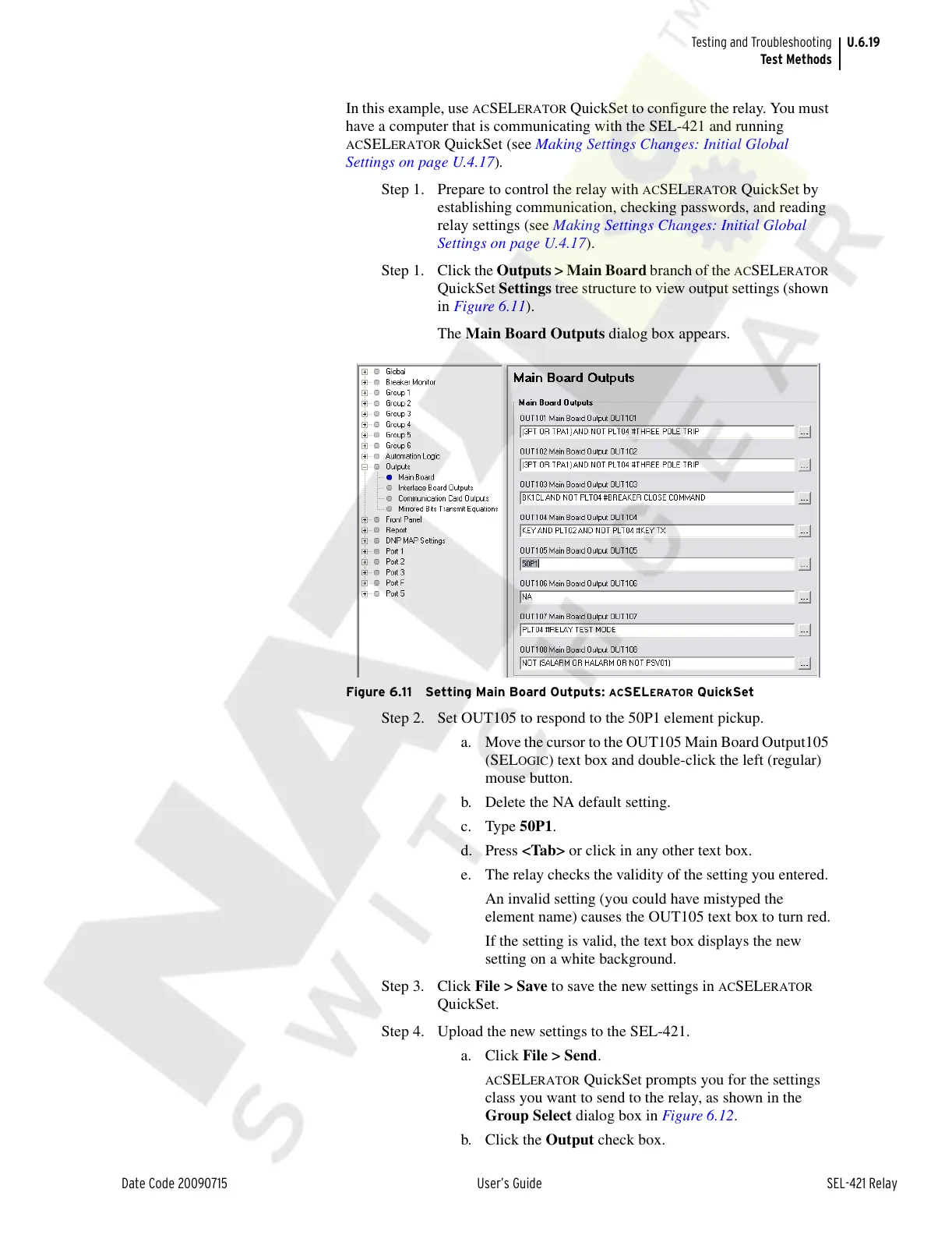
Step 1. Click the Outputs > Main Board branch of the
ACSELERATOR
QuickSet Settings tree structure to view output settings (shown
in Figure 6.11).
The Main Board Outputs dialog box appears.
Figure 6.11 Setting Main Board Outputs: ACSELERATOR QuickSet
Step 2. Set OUT105 to respond to the 50P1 element pickup.
a. Move the cursor to the OUT105 Main Board Output105
(SEL
OGIC) text box and double-click the left (regular)
mouse button.
b. Delete the NA default setting.
c. Type 50P1.
d. Press <Tab> or click in any other text box.
e. The relay checks the validity of the setting you entered.
An invalid setting (you could have mistyped the
element name) causes the OUT105 text box to turn red.
If the setting is valid, the text box displays the new
setting on a white background.
Step 3. Click File > Save to save the new settings in
ACSELERATOR
QuickSet.
Step 4. Upload the new settings to the SEL-421.
a. Click File > Send.
ACSELERATOR QuickSet prompts you for the settings
class you want to send to the relay, as shown in the
Group Select dialog box in Figure 6.12.
b. Click the Output check box.
Courtesy of NationalSwitchgear.com