U.2.48
SEL-421 Relay User’s Guide Date Code 20090715
Installation
Connection
Serial Cables
Using an improper cable can cause numerous problems or failure to operate,
so you must be sure to specify the proper cable for application of your
SEL-421. Several standard SEL communications cables are available for use
with the relay. See EIA-232 Communications Cables on page R.4.3 for
information on recommended serial cables.
The following list provides additional rules and practices you should follow
for successful communication using EIA-232 serial communications devices
and cables:
➤ Route communications cables well away from power and
control circuits. Switching spikes and surges in power and
control circuits can cause noise in the communications circuits
if power and control circuits are not adequately separated from
communications cables.
➤ Keep the length of the communications cables as short as
possible to minimize communications circuit interference and
also to minimize the magnitude of hazardous ground potential
differences that can develop during abnormal power system
conditions.
➤ Ensure that EIA-232 communications cable lengths never
exceed 50 feet, and always use shielded cables for
communications circuit lengths greater than 10 feet.
➤ Modems provide communication over long distances and give
isolation from ground potential differences that are present
between device locations (examples are the SEL-28XX-series
transceivers).
➤ Lower data speed communication is less susceptible to
interference and will transmit greater distances over the same
medium than higher data speeds. Use the lowest data speed that
provides an adequate data transfer rate.
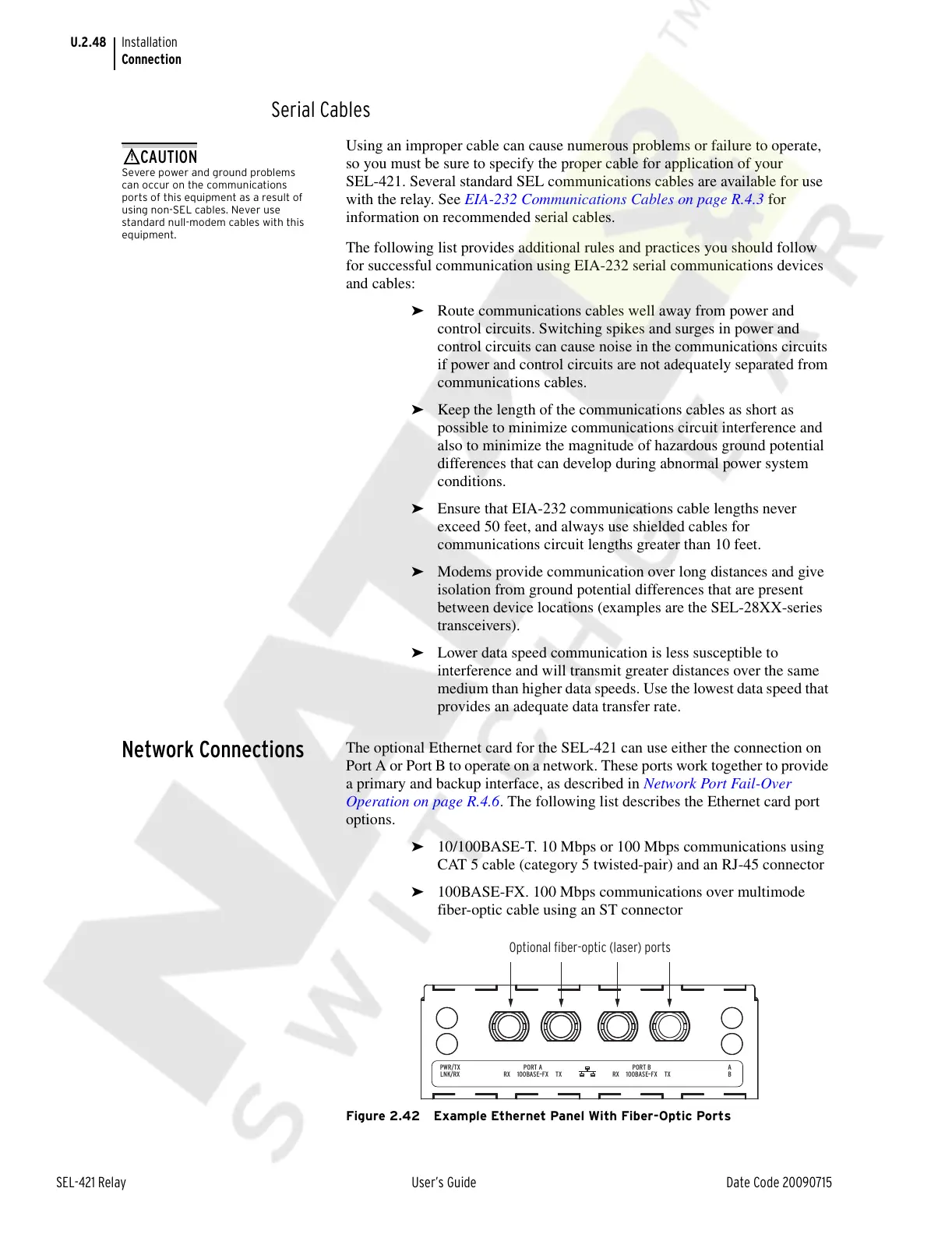
Network Connections
The optional Ethernet card for the SEL-421 can use either the connection on
Port A or Port B to operate on a network. These ports work together to provide
a primary and backup interface, as described in Network Port Fail-Over
Operation on page R.4.6. The following list describes the Ethernet card port
options.
➤ 10/100BASE-T. 10 Mbps or 100 Mbps communications using
CAT 5 cable (category 5 twisted-pair) and an RJ-45 connector
➤ 100BASE-FX. 100 Mbps communications over multimode
fiber-optic cable using an ST connector
Figure 2.42 Example Ethernet Panel With Fiber-Optic Ports
Severe power and ground problems
can occur on the communications
ports of this equipment as a result of
using non-SEL cables. Never use
standard null-modem cables with this
equipment.
Optional fiber-optic (laser) ports
PWR/TX
LNK/RX
A
B100BASE–FX TXRX
PORT A
100BASE–FX TXRX
PORT B
Courtesy of NationalSwitchgear.com