U.2.49
Date Code 20090715 User’s Guide SEL-421 Relay
Installation
Connection
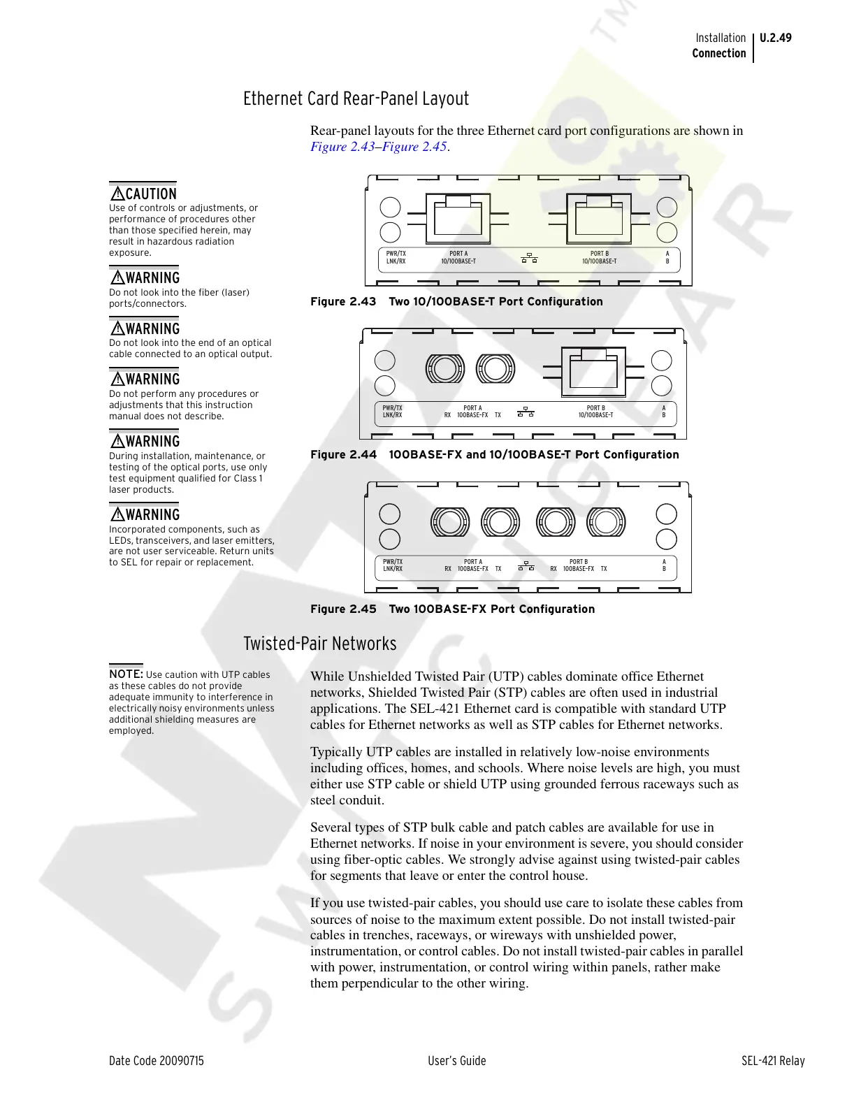
Ethernet Card Rear-Panel Layout
Rear-panel layouts for the three Ethernet card port configurations are shown in
Figure 2.43–Figure 2.45.
Figure 2.43 Two 10/100BASE-T Port Configuration
Figure 2.44 100BASE-FX and 10/100BASE-T Port Configuration
Figure 2.45 Two 100BASE-FX Port Configuration
Twisted-Pair Networks
NOTE: Use caution with UTP cables
as these cables do not provide
adequate immunity to interference in
electrically noisy environments unless
additional shielding measures are
employed.
While Unshielded Twisted Pair (UTP) cables dominate office Ethernet
networks, Shielded Twisted Pair (STP) cables are often used in industrial
applications. The SEL-421 Ethernet card is compatible with standard UTP
cables for Ethernet networks as well as STP cables for Ethernet networks.
Typically UTP cables are installed in relatively low-noise environments
including offices, homes, and schools. Where noise levels are high, you must
either use STP cable or shield UTP using grounded ferrous raceways such as
steel conduit.
Several types of STP bulk cable and patch cables are available for use in
Ethernet networks. If noise in your environment is severe, you should consider
using fiber-optic cables. We strongly advise against using twisted-pair cables
for segments that leave or enter the control house.
If you use twisted-pair cables, you should use care to isolate these cables from
sources of noise to the maximum extent possible. Do not install twisted-pair
cables in trenches, raceways, or wireways with unshielded power,
instrumentation, or control cables. Do not install twisted-pair cables in parallel
with power, instrumentation, or control wiring within panels, rather make
them perpendicular to the other wiring.
PWR/TX
LNK/RX
A
B10/100BASE–T
PORT A
10/100BASE–T
PORT B
Use of controls or adjustments, or
performance of procedures other
than those specified herein, may
result in hazardous radiation
exposure.
Do not look into the fiber (laser)
ports/connectors.
Do not look into the end of an optical
cable connected to an optical output.
Do not perform any procedures or
adjustments that this instruction
manual does not describe.
During installation, maintenance, or
testing of the optical ports, use only
test equipment qualified for Class 1
laser products.
Incorporated components, such as
LEDs, transceivers, and laser emitters,
are not user serviceable. Return units
to SEL for repair or replacement.
PWR/TX
LNK/RX
A
B100BASE–FX TXRX
PORT A
10/100BASE–T
PORT B
PWR/TX
LNK/RX
A
B100BASE–FX TXRX
PORT A
100BASE–FX TXRX
PORT B
Courtesy of NationalSwitchgear.com