U.2.41
Date Code 20090715 User’s Guide SEL-421 Relay
Installation
Connection
Step 21. Reconnect the cable removed in Step 8 and reinstall the relay
front-panel cover.
Step 22. Reattach the rear-panel connections.
Affix the screw terminal connectors to the appropriate 100-
addresses, 200-addresses, and 300-addresses locations on the
rear panel.
Step 23. Reconnect any serial cables that you removed from the EIA-232
PORTS in the disassembly process.
Step 24. Follow your company standard procedure to return the relay to
service.
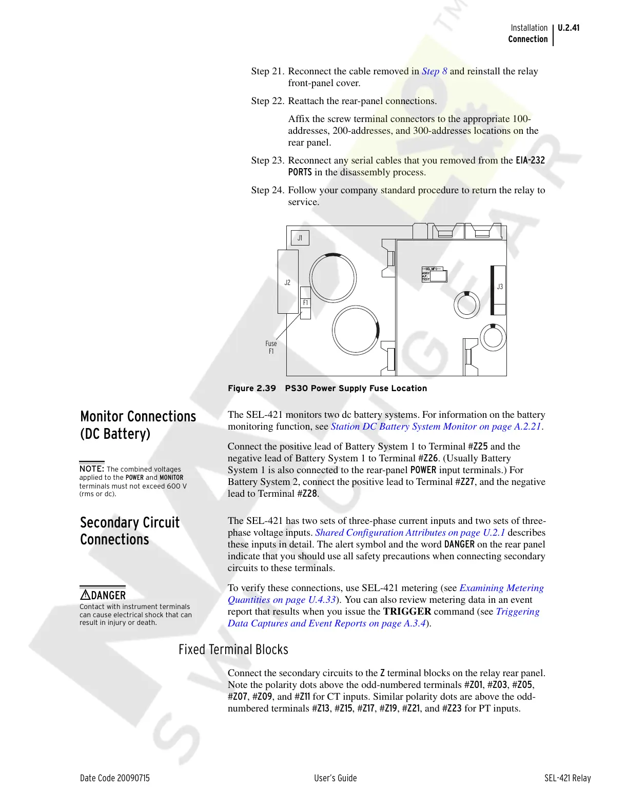
Figure 2.39 PS30 Power Supply Fuse Location
Monitor Connections
(DC Battery)
The SEL-421 monitors two dc battery systems. For information on the battery
monitoring function, see Station DC Battery System Monitor on page A.2.21.
Connect the positive lead of Battery System 1 to Terminal #Z25 and the
negative lead of Battery System 1 to Terminal #Z26. (Usually Battery
System 1 is also connected to the rear-panel POWER input terminals.) For
Battery System 2, connect the positive lead to Terminal #Z27, and the negative
lead to Terminal #Z28.
Secondary Circuit
Connections
The SEL-421 has two sets of three-phase current inputs and two sets of three-
phase voltage inputs. Shared Configuration Attributes on page U.2.1 describes
these inputs in detail. The alert symbol and the word DANGER on the rear panel
indicate that you should use all safety precautions when connecting secondary
circuits to these terminals.
To verify these connections, use SEL-421 metering (see Examining Metering
Quantities on page U.4.33). You can also review metering data in an event
report that results when you issue the TRIGGER command (see Triggering
Data Captures and Event Reports on page A.3.4).
Fixed Terminal Blocks
Connect the secondary circuits to the Z terminal blocks on the relay rear panel.
Note the polarity dots above the odd-numbered terminals #Z01, #Z03, #Z05,
#Z07, #Z09, and #Z11 for CT inputs. Similar polarity dots are above the odd-
numbered terminals #Z13, #Z15, #Z17, #Z19, #Z21, and #Z23 for PT inputs.
NOTE: The combined voltages
applied to the POWER and MONITOR
terminals must not exceed 600 V
(rms or dc).
Contact with instrument terminals
can cause electrical shock that can
result in injury or death.
!
DANGER
Courtesy of NationalSwitchgear.com