U.2.13
Date Code 20090715 User’s Guide SEL-421 Relay
Installation
Plug-In Boards
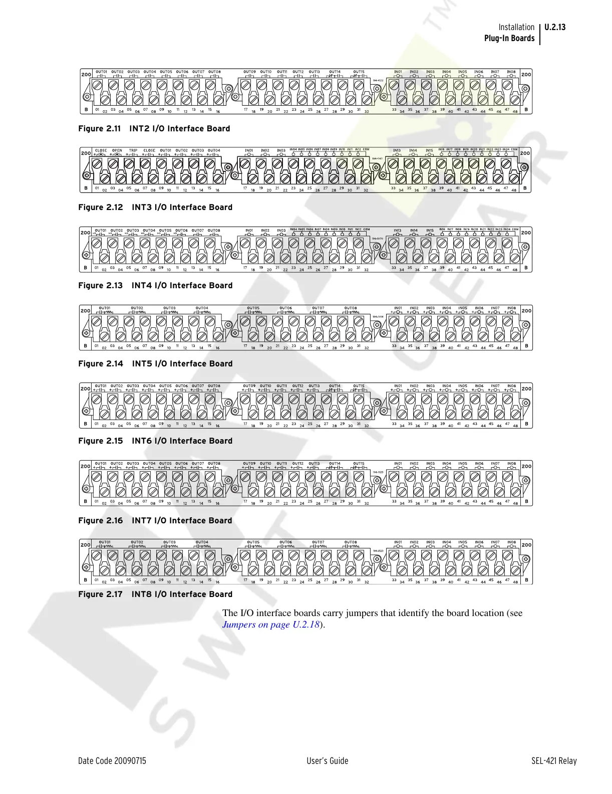
Figure 2.11 INT2 I/O Interface Board
Figure 2.12 INT3 I/O Interface Board
Figure 2.13 INT4 I/O Interface Board
Figure 2.14 INT5 I/O Interface Board
Figure 2.15 INT6 I/O Interface Board
Figure 2.16 INT7 I/O Interface Board
Figure 2.17 INT8 I/O Interface Board
The I/O interface boards carry jumpers that identify the board location (see
Jumpers on page U.2.18).
Courtesy of NationalSwitchgear.com