U.2.27
Date Code 20090715 User’s Guide SEL-421 Relay
Installation
Jumpers
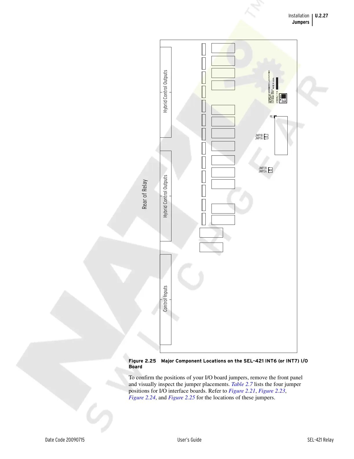
Figure 2.25 Major Component Locations on the SEL-421 INT6 (or INT7) I/O
Board
To confirm the positions of your I/O board jumpers, remove the front panel
and visually inspect the jumper placements. Table 2.7 lists the four jumper
positions for I/O interface boards. Refer to Figure 2.21, Figure 2.23,
Figure 2.24, and Figure 2.25 for the locations of these jumpers.
JMP2A
JMP2B
JMP1A
J8
Control Inputs Hybrid Control Outputs Hybrid Control Outputs
JMP1B
6
Rear of Relay
Courtesy of NationalSwitchgear.com