U.2.32
SEL-421 Relay User’s Guide Date Code 20090715
Installation
Connection
Rear-Panel Layout
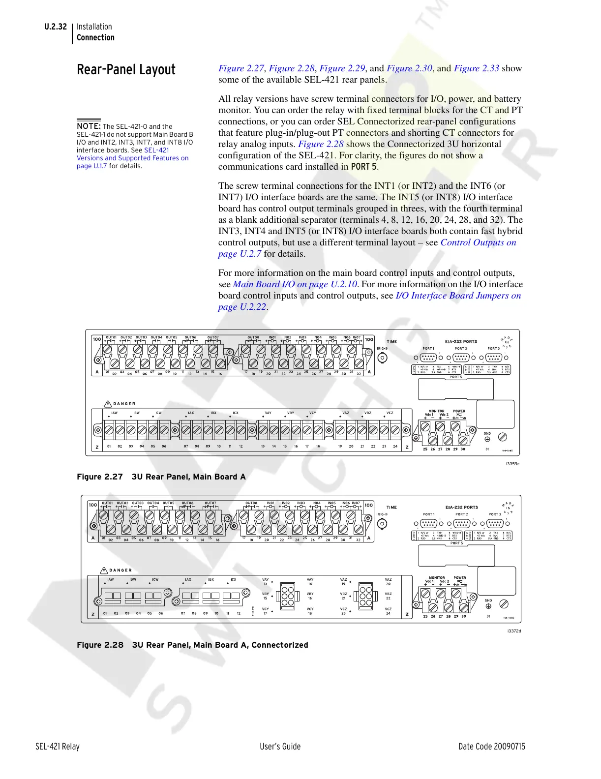
Figure 2.27, Figure 2.28, Figure 2.29, and Figure 2.30, and Figure 2.33 show
some of the available SEL-421 rear panels.
All relay versions have screw terminal connectors for I/O, power, and battery
monitor. You can order the relay with fixed terminal blocks for the CT and PT
connections, or you can order SEL Connectorized rear-panel configurations
that feature plug-in/plug-out PT connectors and shorting CT connectors for
relay analog inputs. Figure 2.28 shows the Connectorized 3U horizontal
configuration of the SEL-421. For clarity, the figures do not show a
communications card installed in PORT 5.
The screw terminal connections for the INT1 (or INT2) and the INT6 (or
INT7) I/O interface boards are the same. The INT5 (or INT8) I/O interface
board has control output terminals grouped in threes, with the fourth terminal
as a blank additional separator (terminals 4, 8, 12, 16, 20, 24, 28, and 32). The
INT3, INT4 and INT5 (or INT8) I/O interface boards both contain fast hybrid
control outputs, but use a different terminal layout – see Control Outputs on
page U.2.7 for details.
For more information on the main board control inputs and control outputs,
see Main Board I/O on page U.2.10. For more information on the I/O interface
board control inputs and control outputs, see I/O Interface Board Jumpers on
page U.2.22.
Figure 2.27 3U Rear Panel, Main Board A
Figure 2.28 3U Rear Panel, Main Board A, Connectorized
NOTE: The SEL-421-0 and the
SEL-421-1 do not support Main Board B
I/O and INT2, INT3, INT7, and INT8 I/O
interface boards. See SEL-421
Versions and Supported Features on
page U.1.7 for details.
Courtesy of NationalSwitchgear.com