U.2.28
SEL-421 Relay User’s Guide Date Code 20090715
Installation
Jumpers
The I/O board control address has a hundreds-series prefix attached to the
control inputs and control outputs for that particular I/O board chassis slot. A
4U chassis has a 200-addresses slot for inputs IN201, IN202, etc., and outputs
OUT201, OUT202, etc. A 5U chassis has a 200-addresses slot and a 300-
addresses slot.
The drawout tray on which each I/O board is mounted is keyed. See Installing
Optional I/O Interface Boards on page U.2.15 for information on the key
positions for the 200-addresses slot trays and the 300-addresses slot trays.
Changing I/O Interface Board Jumpers
Change the I/O interface board jumpers only when you move the slot position
of an I/O board. You must remove the I/O interface boards to access the
jumpers. Perform the following steps to change jumpers on an SEL-421 I/O
interface board:
Step 1. Follow your company standard to remove the relay from
service.
Step 2. Disconnect power from the SEL-421.
Step 3. Retain the GND connection, if possible, and ground the
equipment to an ESD mat.
Step 4. Remove the communications cable connected to the front-panel
serial port, if applicable.
Step 5. Loosen the four front-panel screws (they remain attached to the
front panel), and remove the relay front panel.
Step 6. Remove the 34-pin ribbon cable from the front panel by
pushing the extraction ears away from the connector.
Step 7. Disconnect the power, the interface board, and the analog input
board cables from the main board.
Step 8. Pull out the drawout assembly containing the I/O interface
board.
Step 9. Locate the jumper you want to change.
The I/O interface board jumpers are located near the front of
each I/O board, and near the interface board connector, as
shown for each type of interface board in Figure 2.21 through
Figure 2.25.
Step 10. Install or remove the jumper as needed (see Ta bl e 2. 7 for
jumper position descriptions).
Step 11. Reinstall the interface board, and reconnect the power, the
interface board, and the analog input board cables.
Step 12. Reconnect the cable removed in Step 6 and reinstall the relay
front-panel cover.
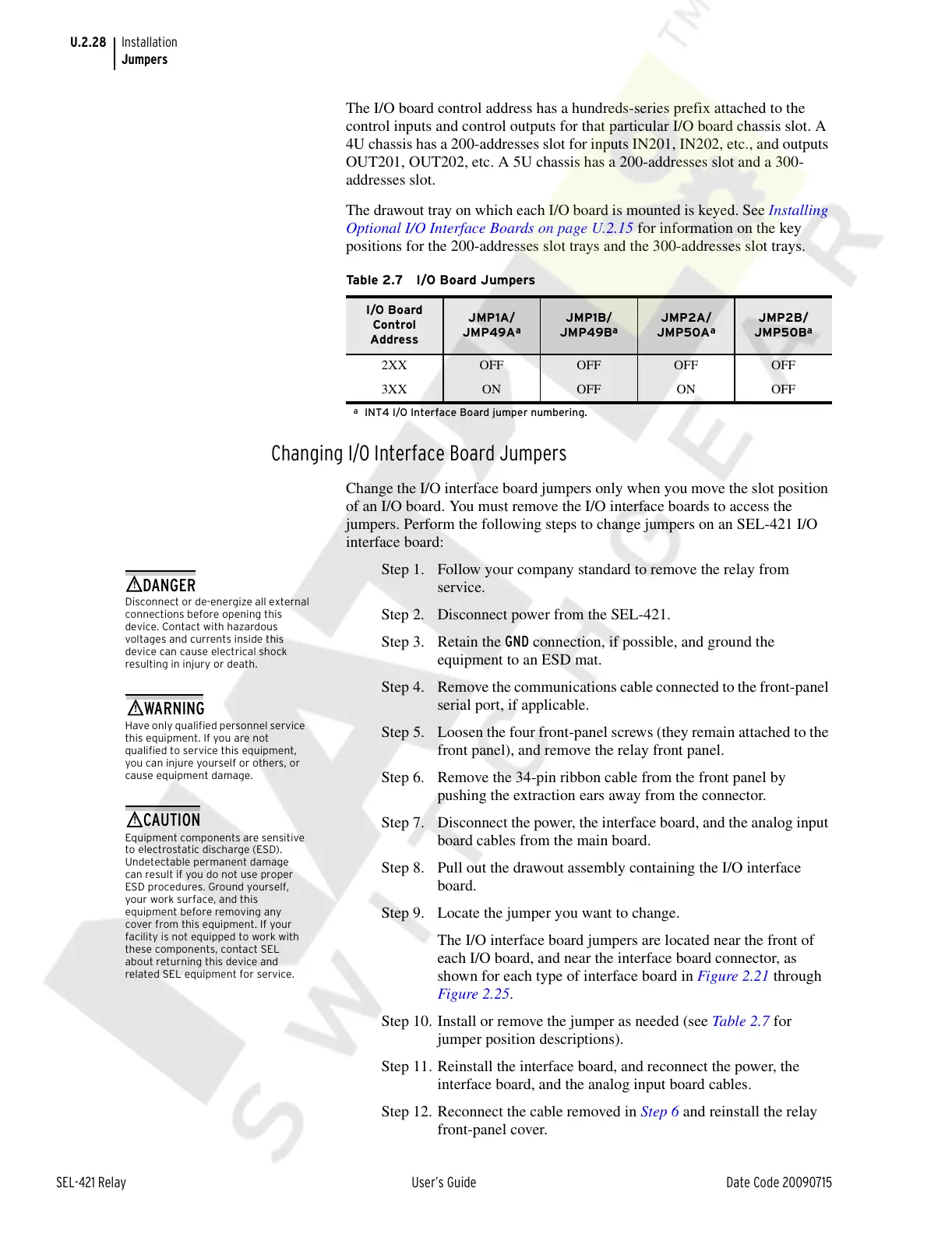
Table 2.7 I/O Board Jumpers
I/O Board
Control
Address
JMP1A/
JMP49A
a
a
INT4 I/O Interface Board jumper numbering.
JMP1B/
JMP49B
a
JMP2A/
JMP50A
a
JMP2B/
JMP50B
a
2XX OFF OFF OFF OFF
3XX ON OFF ON OFF
Disconnect or de-energize all external
connections before opening this
device. Contact with hazardous
voltages and currents inside this
device can cause electrical shock
resulting in injury or death.
!
DANGER
Have only qualified personnel service
this equipment. If you are not
qualified to service this equipment,
you can injure yourself or others, or
cause equipment damage.
!
WARNING
Equipment components are sensitive
to electrostatic discharge (ESD).
Undetectable permanent damage
can result if you do not use proper
ESD procedures. Ground yourself,
your work surface, and this
equipment before removing any
cover from this equipment. If your
facility is not equipped to work with
these components, contact SEL
about returning this device and
related SEL equipment for service.
!
CAUTION
Courtesy of NationalSwitchgear.com