U.2.5
Date Code 20090715 User’s Guide SEL-421 Relay
Installation
Shared Configuration Attributes
The relay also accepts two sets of three-phase, four-wire (wye) potentials from
power system PT or CCVT (coupling-capacitor voltage transformer)
secondaries:
➤ VAY, V B Y, a n d V C Y
➤ VAZ, VBZ, and VCZ
The nominal line-to-neutral input voltage for the PT inputs is 67 volts with a
range of 0–300 volts. The PT burden is less than 0.5 VA
at 67 volts, L-N. See
AC Voltage Inputs on page U.1.13 for complete PT input specifications.
Some applications do not use all three phases of a source; for example, voltage
synchronization sources can be single phase. See Section 1: Protection
Application Examples in the Applications Handbook for examples of
connections to the potential inputs.
See Secondary Circuit Connections on page U.2.41 for information on
connecting power system secondary circuits to these inputs.
Control Inputs
Direct Coupled
The SEL-421 Main Board A inputs, and the inputs on the optional I/O
interface boards (INT1, INT5, or INT6 I /O boards—see Models and Options
on page U.1.5), are direct-coupled, high-impedance control inputs. Use these
inputs for monitoring on/off and logical change-of-state conditions of power
system equipment. These high-isolation control inputs are polarity-sensitive
circuits. You cannot damage these inputs with a reverse polarity connection,
although the relay will not detect input changes with a reverse-polarity input.
For more information on control input specifications, see Control Inputs on
page U.1.14.
Inputs can be independent or common. Independent inputs have two separate
ground-isolated connections to a high-isolation ADC (analog to digital
converter). There are no internal connections among independent inputs.
Common inputs share one input leg in common; all input legs of common
inputs are ground-isolated. Each pair of common inputs is isolated from all
other pairs.
Nominal current draw for these inputs is very low (4 mA or less) with an input
voltage range of 15 Vdc to 265 Vdc. You can adjust the level at which these
inputs assert (and deassert) and can also debounce the control inputs. See
Global Settings on page R.10.4 for the default settings and more information.
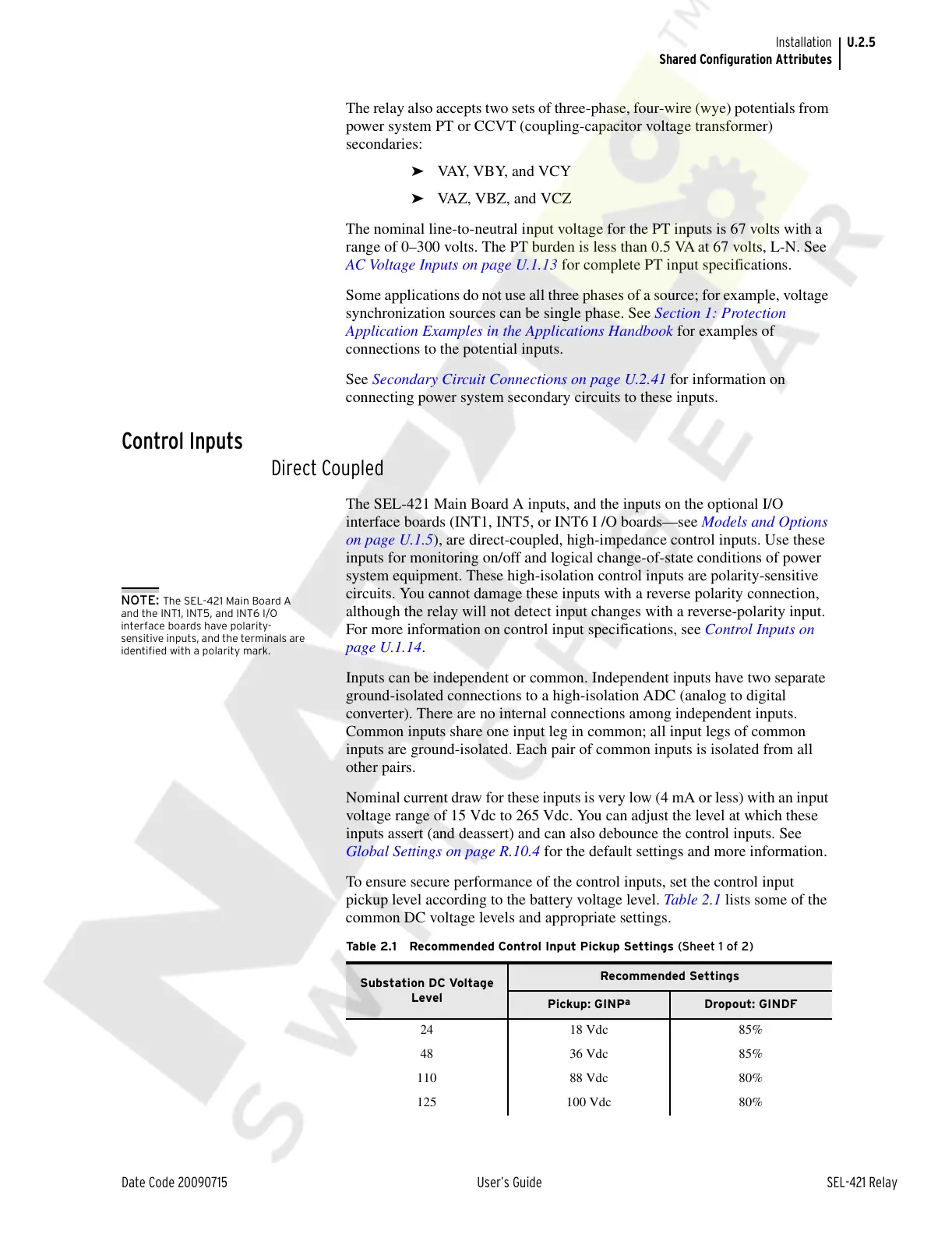
To ensure secure performance of the control inputs, set the control input
pickup level according to the battery voltage level. Table 2.1 lists some of the
common DC voltage levels and appropriate settings.
Table 2.1 Recommended Control Input Pickup Settings (Sheet 1 of 2)
Substation DC Voltage
Level
Recommended Settings
Pickup: GINP
a
Dropout: GINDF
24 18 Vdc 85%
48 36 Vdc 85%
110 88 Vdc 80%
125 100 Vdc 80%
NOTE: The SEL-421 Main Board A
and the INT1, INT5, and INT6 I/O
interface boards have polarity-
sensitive inputs, and the terminals are
identified with a polarity mark.
Courtesy of NationalSwitchgear.com