U.4.58
SEL-421 Relay User’s Guide Date Code 20090715
Basic Relay Operations
Operating the Relay Inputs and Outputs
Pulsing a Control Output: Front Panel
The procedure in the following steps shows you how to use the front-panel
display and navigation pushbuttons to check for proper operation of the
SEL-421 control outputs. See Section 5: Front-Panel Operations for
information on using the relay front panel.
Step 1. Attach an indicating device (an ohmmeter with a beep sounder
or a test set) to the terminals for control output OUT104.
This output is a Standard control output and is not polarity
sensitive.
For more information on connecting control outputs, see
Control Outputs on page U.2.7.
Step 2. View the front-panel display.
After applying power to the relay, note that the LCD shows a
sequence of screens called the
ROTATING DISPLAY.
(Also, if you do not operate the front panel for a certain period,
the relay will enter front-panel time-out mode and you will see
the sequential screens of the
ROTATING DISPLAY.)
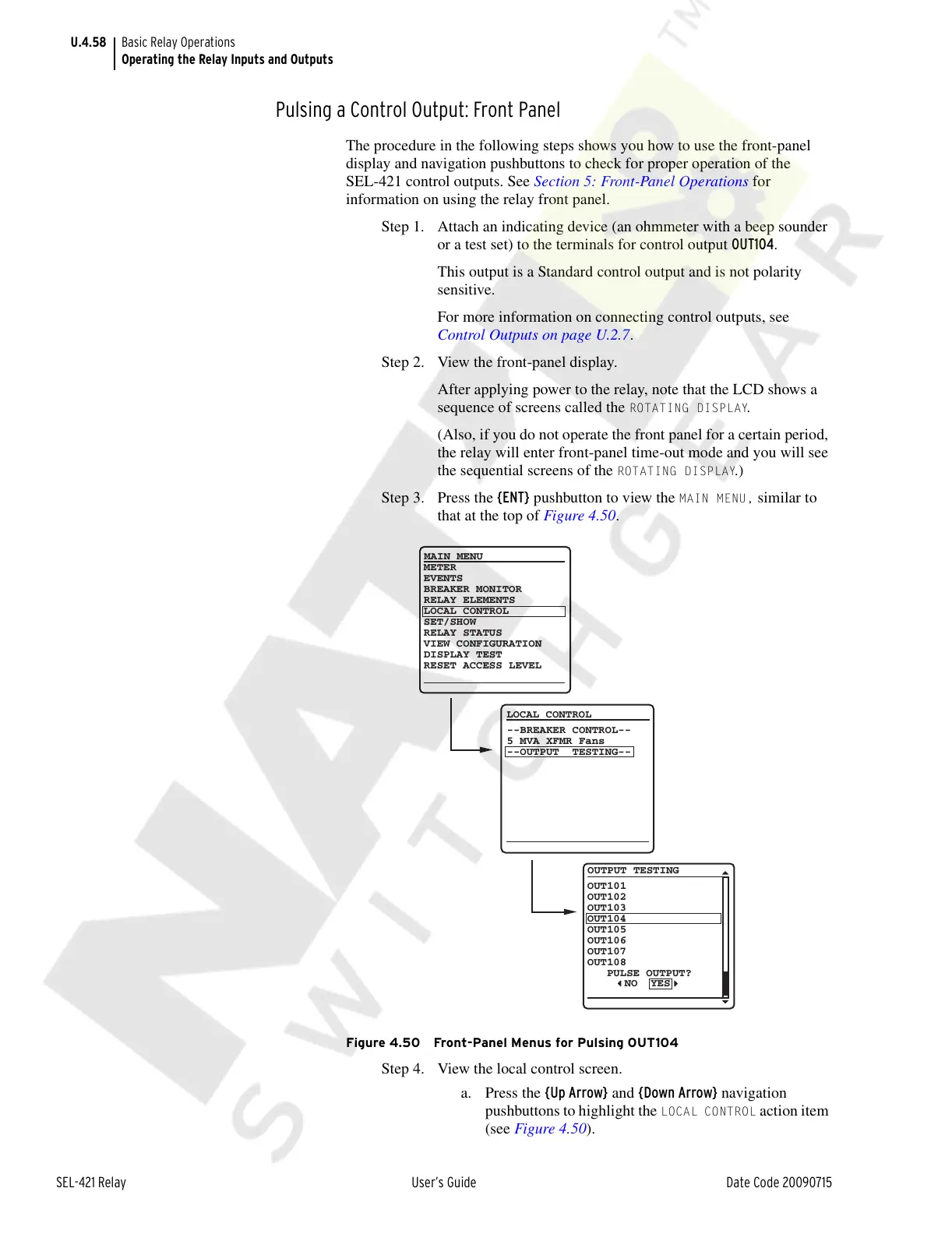
Step 3. Press the {ENT} pushbutton to view the
MAIN MENU, similar to
that at the top of Figure 4.50.
Figure 4.50 Front-Panel Menus for Pulsing OUT104
Step 4. View the local control screen.
a. Press the {Up Arrow} and {Down Arrow} navigation
pushbuttons to highlight the
LOCAL CONTROL action item
(see Figure 4.50).
OUT101
OUT102
OUT103
OUT104
OUT105
OUT106
OUT107
OUT108
PULSE OUTPUT?
OUTPUT TESTING
NO YES
METER
EVENTS
BREAKER MONITOR
RELAY ELEMENTS
LOCAL CONTROL
SET/SHOW
RELAY STATUS
VIEW CONFIGURATION
DISPLAY TEST
RESET ACCESS LEVEL
MAIN MENU
LOCAL CONTROL
--BREAKER CONTROL--
5 MVA XFMR Fans
--OUTPUT TESTING--
Courtesy of NationalSwitchgear.com