U.4.13
Date Code 20090715 User’s Guide SEL-421 Relay
Basic Relay Operations
Making Simple Settings Changes
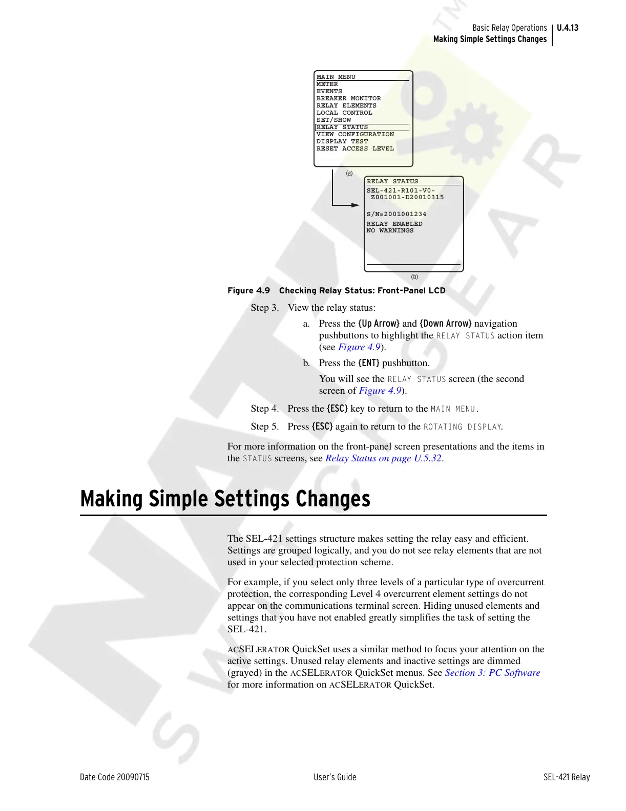
Figure 4.9 Checking Relay Status: Front-Panel LCD
Step 3. View the relay status:
a. Press the {Up Arrow} and {Down Arrow} navigation
pushbuttons to highlight the
RELAY STATUS action item
(see Figure 4.9).
b. Press the {ENT} pushbutton.
You will see the
RELAY STATUS screen (the second
screen of Figure 4.9).
Step 4. Press the {ESC} key to return to the
MAIN MENU.
Step 5. Press {ESC} again to return to the ROTATING DISPLAY.
For more information on the front-panel screen presentations and the items in
the
STATUS screens, see Relay Status on page U.5.32.
Making Simple Settings Changes
The SEL-421 settings structure makes setting the relay easy and efficient.
Settings are grouped logically, and you do not see relay elements that are not
used in your selected protection scheme.
For example, if you select only three levels of a particular type of overcurrent
protection, the corresponding Level 4 overcurrent element settings do not
appear on the communications terminal screen. Hiding unused elements and
settings that you have not enabled greatly simplifies the task of setting the
SEL-421.
ACSELERATOR QuickSet uses a similar method to focus your attention on the
active settings. Unused relay elements and inactive settings are dimmed
(grayed) in the
ACSELERATOR QuickSet menus. See Section 3: PC Software
for more information on
ACSELERATOR QuickSet.
(a)
(b)
METER
EVENTS
BREAKER MONITOR
RELAY ELEMENTS
LOCAL CONTROL
SET/SHOW
RELAY STATUS
VIEW CONFIGURATION
DISPLAY TEST
RESET ACCESS LEVEL
MAIN MENU
RELAY STATUS
SEL-421-R101-V0-
Z001001-D20010315
S/N=2001001234
RELAY ENABLED
NO WARNINGS
Courtesy of NationalSwitchgear.com