U.5.36
SEL-421 Relay User’s Guide Date Code 20090715
Front-Panel Operations
Operation and Target LEDs
Operation and Target LEDs
The SEL-421 gives you at-a-glance confirmation of relay conditions via
operation and target LEDs. These LEDs are located in the middle of the relay
front panel. The SEL-421 provides either 16 or 24 LEDs depending on
ordering option.
You can reprogram all of these indicators except the ENABLED and TRIP LEDs
to reflect other operating conditions than the factory default programming
described in this subsection. Settings Tn_LED are SEL
OGIC control equations
that, when asserted during a relay trip event, light the corresponding LED.
Parameter n is a number from 1 through 24 that indicates each LED. LED
positions are described in parenthesis next to each LED in Figure 5.43.
Program settings TnLEDL := Y to latch the LEDs during trip events; when
you set TnLEDL := N, the trip latch supervision has no effect and the LED
follows the state of the Tn_LED SEL
OGIC control equation. The relay reports
these targets in event reports; set the alias name listed in the report (up to eight
characters) with settings TnLEDA. The asserted and deasserted colors for the
LED are determined with settings TnLEDC. Options include red, green,
amber, or off.
After setting the target LEDs, issue the TAR R command to reset the target
LEDs. For a concise listing of the default programming on the front-panel
LEDs, see Front-Panel Settings on page R.10.37.
Use the slide-in labels to mark the LEDs with custom names. Included on the
SEL-421 Product Literature CD are Customer Label Templates to print labels
for the slide-in label carrier.
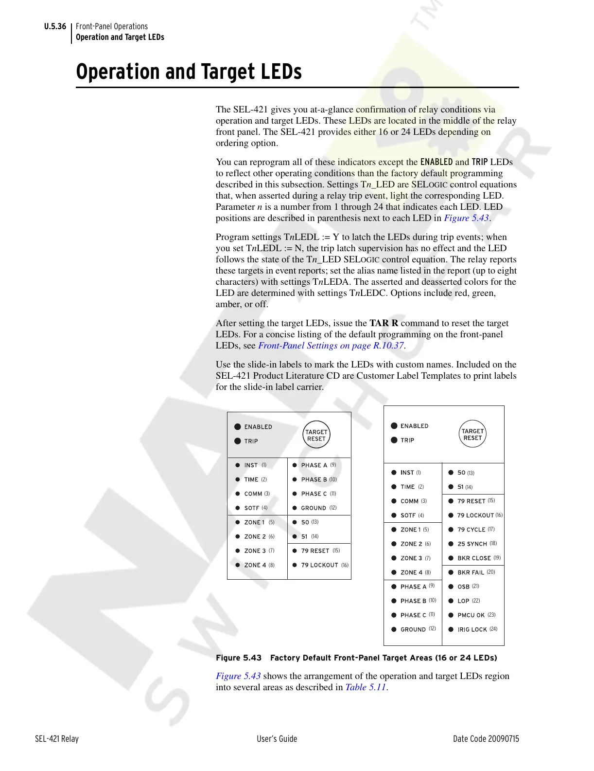
Figure 5.43 Factory Default Front-Panel Target Areas (16 or 24 LEDs)
Figure 5.43 shows the arrangement of the operation and target LEDs region
into several areas as described in Table 5.11.
(1)
(2)
(3)
(4)
(5)
(6)
(7)
(8)
(9)
(10)
(11)
(12)
(13)
(14)
(15)
(16)
(1)
(2)
(3)
(4)
(5)
(6)
(7)
(8)
(9)
(10)
(11)
(12)
(13)
(14)
(15)
(16)
(17)
(18)
(19)
(20)
(21)
(22)
(23)
(24)
Courtesy of NationalSwitchgear.com