U.4.70
SEL-421 Relay User’s Guide Date Code 20090715
Basic Relay Operations
Operating the Relay Inputs and Outputs
Step 8. Set the control input IN101 debounce time.
For this example, assume that the auxiliary contacts are slow
and noisy; you must provide a slightly longer debounce time
for these contacts.
a. Double-click the mouse cursor (or press <Tab>) to
highlight IN101PU Input IN101 pickup delay.
b. Delete the present setting by pressing <Delete>.
c. Type 0.25 <Enter>.
d. Similarly change the IN101DO Input IN101 Dropout
Delay to 0.25.
The relay checks the new value and enters the value in
the
ACSELERATOR QuickSet database.
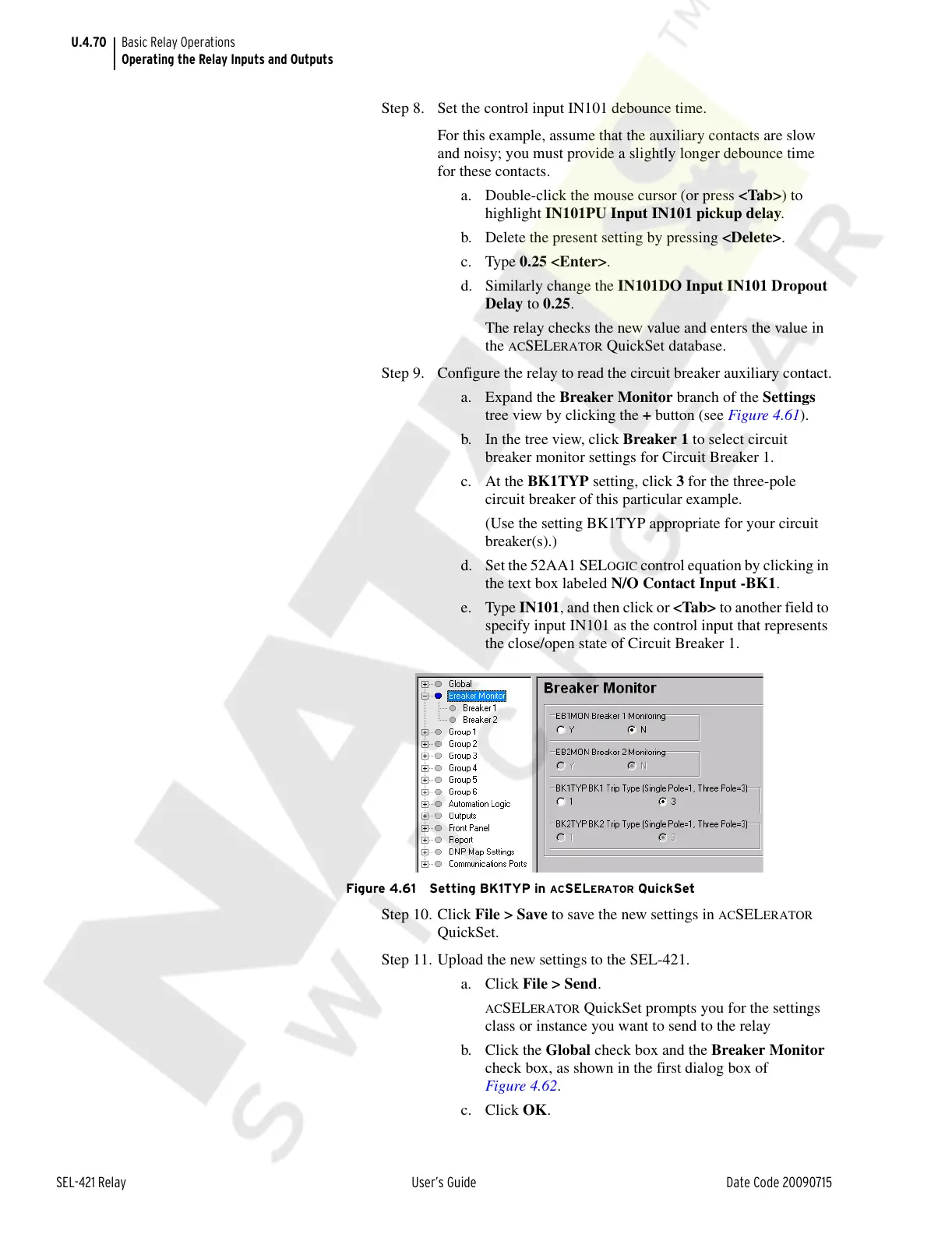
Step 9. Configure the relay to read the circuit breaker auxiliary contact.
a. Expand the Breaker Monitor branch of the Settings
tree view by clicking the + button (see Figure 4.61).
b. In the tree view, click Breaker 1 to select circuit
breaker monitor settings for Circuit Breaker 1.
c. At the BK1TYP setting, click 3 for the three-pole
circuit breaker of this particular example.
(Use the setting BK1TYP appropriate for your circuit
breaker(s).)
d. Set the 52AA1 SEL
OGIC control equation by clicking in
the text box labeled N/O Contact Input -BK1.
e. Type IN101, and then click or <Tab> to another field to
specify input IN101 as the control input that represents
the close/open state of Circuit Breaker 1.
Figure 4.61 Setting BK1TYP in ACSELERATOR QuickSet
Step 10. Click File > Save to save the new settings in ACSELERATOR
QuickSet.
Step 11. Upload the new settings to the SEL-421.
a. Click File > Send.
ACSELERATOR QuickSet prompts you for the settings
class or instance you want to send to the relay
b. Click the Global check box and the Breaker Monitor
check box, as shown in the first dialog box of
Figure 4.62.
c. Click OK.
Courtesy of NationalSwitchgear.com