U.2.37
Date Code 20090715 User’s Guide SEL-421 Relay
Installation
Connection
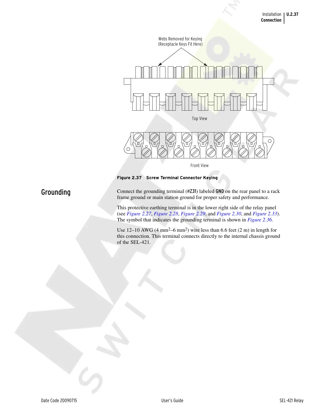
Figure 2.37 Screw Terminal Connector Keying
Grounding
Connect the grounding terminal (#Z31) labeled GND on the rear panel to a rack
frame ground or main station ground for proper safety and performance.
This protective earthing terminal is in the lower right side of the relay panel
(see Figure 2.27, Figure 2.28, Figure 2.29, and Figure 2.30, and Figure 2.33).
The symbol that indicates the grounding terminal is shown in Figure 2.36.
Use 12–10 AWG (4 mm
2
–6 mm
2
) wire less than 6.6 feet (2 m) in length for
this connection. This terminal connects directly to the internal chassis ground
of the SEL-421.
Webs Removed for Keying
(Receptacle Keys Fit Here)
Top View
Front View
Courtesy of NationalSwitchgear.com