U.4.21
Date Code 20090715 User’s Guide SEL-421 Relay
Basic Relay Operations
Making Simple Settings Changes
Display Points and Aliases
(Boolean) : RWB Name, “Alias”, “Set String”, “Clear String”, “Text Size”
(Analog) : Analog Quantity Name, “User Text and Formatting”, “Text Size”
1:
? IN101,CB1,CLOSED,OPEN <Enter>
2:
? IN102,CB2,CLOSED,OPEN <Enter>
3:
? LIST <Enter>
1: IN101,"CB1","CLOSED","OPEN",S
2: IN102,"CB2","CLOSED","OPEN",S
3:
? IN105,"5 MVA XFMR Fans”,ON,OFF <Enter>
4:
?
END <Enter>
•
•
•
Display Points and Aliases
(Boolean) : RWB Name, “Alias”, “Set String”, “Clear String”, “Text Size”
(Analog) : Analog Quantity Name, “User Text and Formatting”, “Text Size”
1: IN101,"CB1","CLOSED","OPEN",S
2: IN102,"CB2","CLOSED","OPEN",S
3: IN105,"5 MVA XFMR Fans","ON","OFF",S
•
•
•
Save settings (Y,N) ? Y <Enter>
Saving Settings, Please Wait...........
Settings Saved
=>>
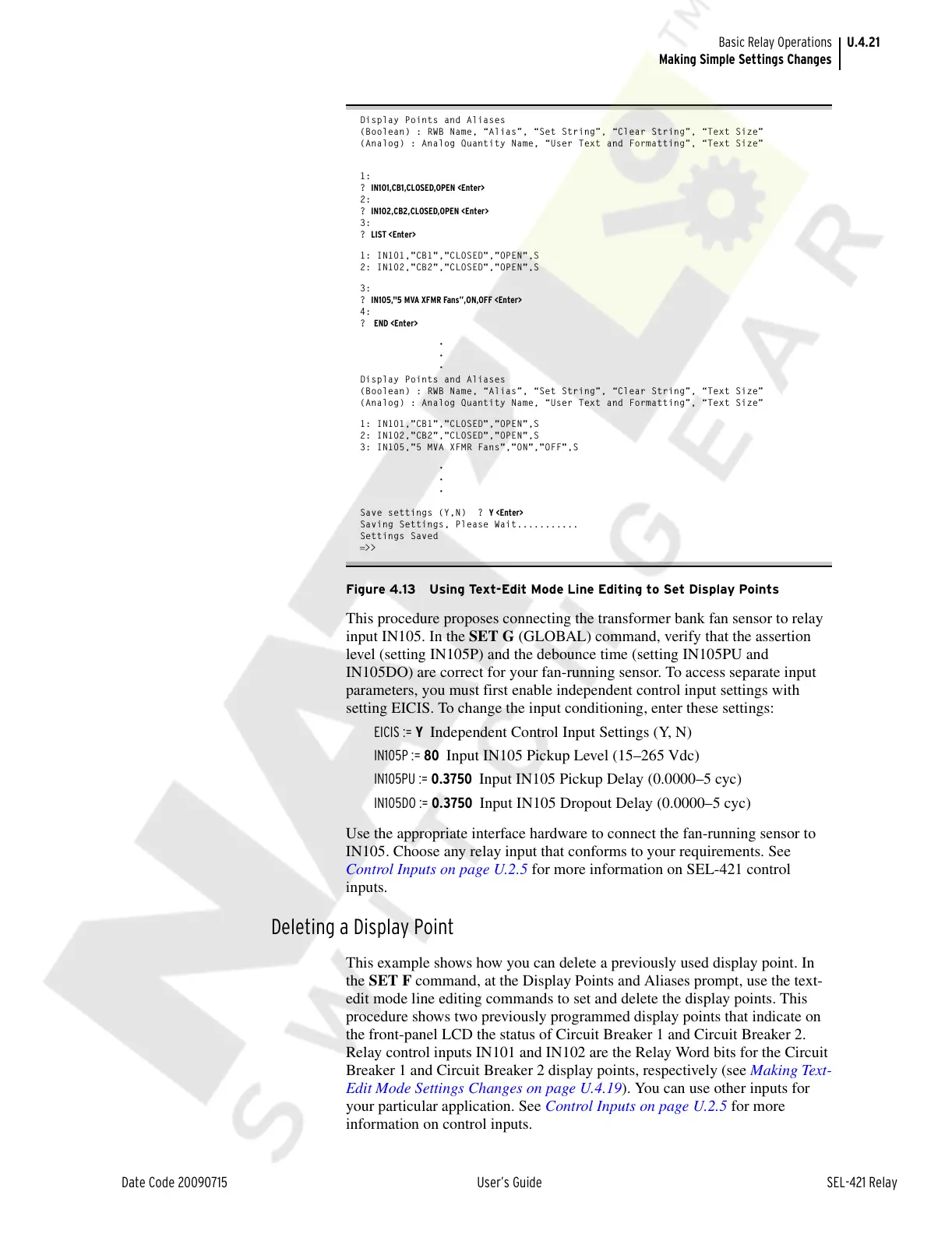
Figure 4.13 Using Text-Edit Mode Line Editing to Set Display Points
This procedure proposes connecting the transformer bank fan sensor to relay
input IN105. In the SET G (GLOBAL) command, verify that the assertion
level (setting IN105P) and the debounce time (setting IN105PU and
IN105DO) are correct for your fan-running sensor. To access separate input
parameters, you must first enable independent control input settings with
setting EICIS. To change the input conditioning, enter these settings:
EICIS := Y Independent Control Input Settings (Y, N)
IN105P := 80 Input IN105 Pickup Level (15–265 Vdc)
IN105PU := 0.3750 Input IN105 Pickup Delay (0.0000–5 cyc)
IN105DO := 0.3750 Input IN105 Dropout Delay (0.0000–5 cyc)
Use the appropriate interface hardware to connect the fan-running sensor to
IN105. Choose any relay input that conforms to your requirements. See
Control Inputs on page U.2.5 for more information on SEL-421 control
inputs.
Deleting a Display Point
This example shows how you can delete a previously used display point. In
the SET F command, at the Display Points and Aliases prompt, use the text-
edit mode line editing commands to set and delete the display points. This
procedure shows two previously programmed display points that indicate on
the front-panel LCD the status of Circuit Breaker 1 and Circuit Breaker 2.
Relay control inputs IN101 and IN102 are the Relay Word bits for the Circuit
Breaker 1 and Circuit Breaker 2 display points, respectively (see Making Text-
Edit Mode Settings Changes on page U.4.19). You can use other inputs for
your particular application. See Control Inputs on page U.2.5 for more
information on control inputs.
Courtesy of NationalSwitchgear.com