U.5.24
SEL-421 Relay User’s Guide Date Code 20090715
Front-Panel Operations
Front-Panel Menus and Screens
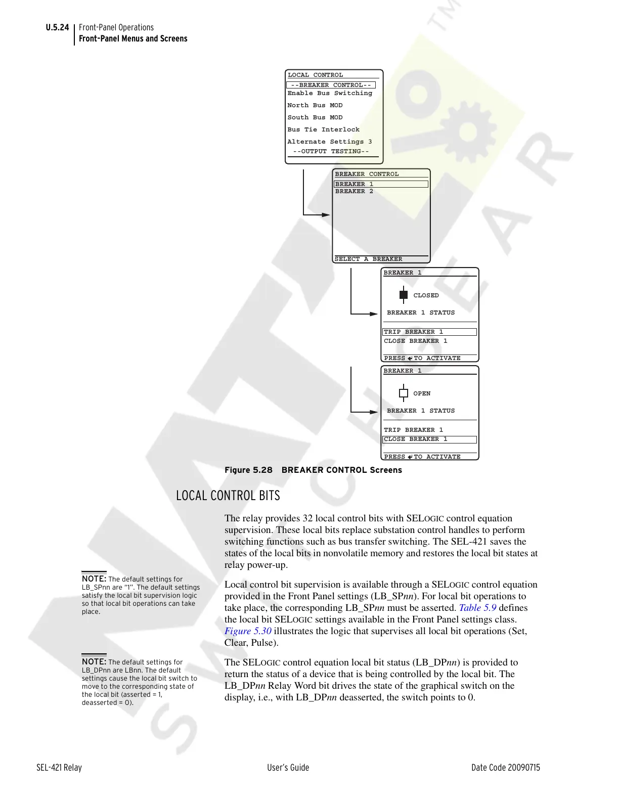
Figure 5.28 BREAKER CONTROL Screens
LOCAL CONTROL BITS
The relay provides 32 local control bits with SELOGIC control equation
supervision. These local bits replace substation control handles to perform
switching functions such as bus transfer switching. The SEL-421 saves the
states of the local bits in nonvolatile memory and restores the local bit states at
relay power-up.
Local control bit supervision is available through a SEL
OGIC control equation
provided in the Front Panel settings (LB_SPnn). For local bit operations to
take place, the corresponding LB_SPnn must be asserted. Table 5.9 defines
the local bit SEL
OGIC settings available in the Front Panel settings class.
Figure 5.30 illustrates the logic that supervises all local bit operations (Set,
Clear, Pulse).
The SEL
OGIC control equation local bit status (LB_DPnn) is provided to
return the status of a device that is being controlled by the local bit. The
LB_DPnn Relay Word bit drives the state of the graphical switch on the
display, i.e., with LB_DPnn deasserted, the switch points to 0.
--BREAKER CONTROL--
--OUTPUT TESTING--
LOCAL CONTROL
Enable Bus Switching
North Bus MOD
South Bus MOD
Bus Tie Interlock
Alternate Settings 3
BREAKER 1
BREAKER 2
SELECT A BREAKER
BREAKER CONTROL
TRIP BREAKER 1
CLOSE BREAKER 1
BREAKER 1
CLOSED
BREAKER 1 STATUS
TRIP BREAKER 1
CLOSE BREAKER 1
BREAKER 1
OPEN
BREAKER 1 STATUS
PRESS TO ACTIVATE
PRESS TO ACTIVATE
NOTE: The default settings for
LB_SPnn are “1”. The default settings
satisfy the local bit supervision logic
so that local bit operations can take
place.
NOTE: The default settings for
LB_DPnn are LBnn. The default
settings cause the local bit switch to
move to the corresponding state of
the local bit (asserted = 1,
deasserted = 0).
Courtesy of NationalSwitchgear.com