U.6.43
Date Code 20090715 User’s Guide SEL-421 Relay
Testing and Troubleshooting
Relay Troubleshooting
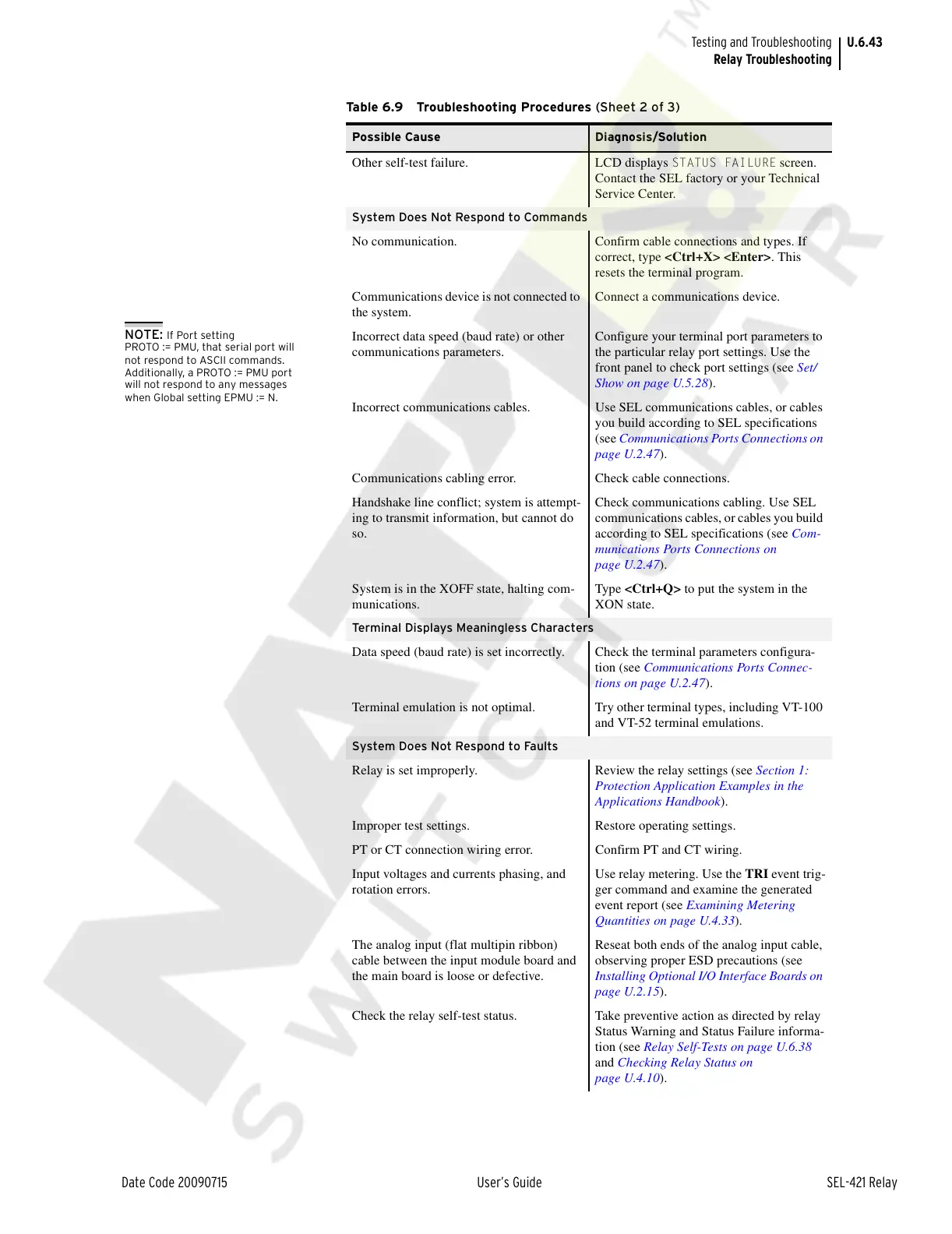
Other self-test failure. LCD displays STATUS FAILURE screen.
Contact the SEL factory or your Technical
Service Center.
System Does Not Respond to Commands
No communication. Confirm cable connections and types. If
correct, type <Ctrl+X> <Enter>. This
resets the terminal program.
Communications device is not connected to
the system.
Connect a communications device.
Incorrect data speed (baud rate) or other
communications parameters.
Configure your terminal port parameters to
the particular relay port settings. Use the
front panel to check port settings (see Set/
Show on page U.5.28).
Incorrect communications cables. Use SEL communications cables, or cables
you build according to SEL specifications
(see Communications Ports Connections on
page U.2.47).
Communications cabling error. Check cable connections.
Handshake line conflict; system is attempt-
ing to transmit information, but cannot do
so.
Check communications cabling. Use SEL
communications cables, or cables you build
according to SEL specifications (see Com-
munications Ports Connections on
page U.2.47).
System is in the XOFF state, halting com-
munications.
Type <Ctrl+Q> to put the system in the
XON state.
Terminal Displays Meaningless Characters
Data speed (baud rate) is set incorrectly. Check the terminal parameters configura-
tion (see Communications Ports Connec-
tions on page U.2.47).
Terminal emulation is not optimal. Try other terminal types, including VT-100
and VT-52 terminal emulations.
System Does Not Respond to Faults
Relay is set improperly. Review the relay settings (see Section 1:
Protection Application Examples in the
Applications Handbook).
Improper test settings. Restore operating settings.
PT or CT connection wiring error. Confirm PT and CT wiring.
Input voltages and currents phasing, and
rotation errors.
Use relay metering. Use the TRI event trig-
ger command and examine the generated
event report (see Examining Metering
Quantities on page U.4.33).
The analog input (flat multipin ribbon)
cable between the input module board and
the main board is loose or defective.
Reseat both ends of the analog input cable,
observing proper ESD precautions (see
Installing Optional I/O Interface Boards on
page U.2.15).
Check the relay self-test status. Take preventive action as directed by relay
Status Warning and Status Failure informa-
tion (see Relay Self-Tests on page U.6.38
and Checking Relay Status on
page U.4.10).
Table 6.9 Troubleshooting Procedures (Sheet 2 of 3)
Possible Cause Diagnosis/Solution
NOTE: If Port setting
PROTO := PMU, that serial port will
not respond to ASCII commands.
Additionally, a PROTO := PMU port
will not respond to any messages
when Global setting EPMU := N.
Courtesy of NationalSwitchgear.com