U.A.18
SEL-421 Relay User’s Guide Date Code 20090715
Firmware and Manual Versions
Instruction Manual
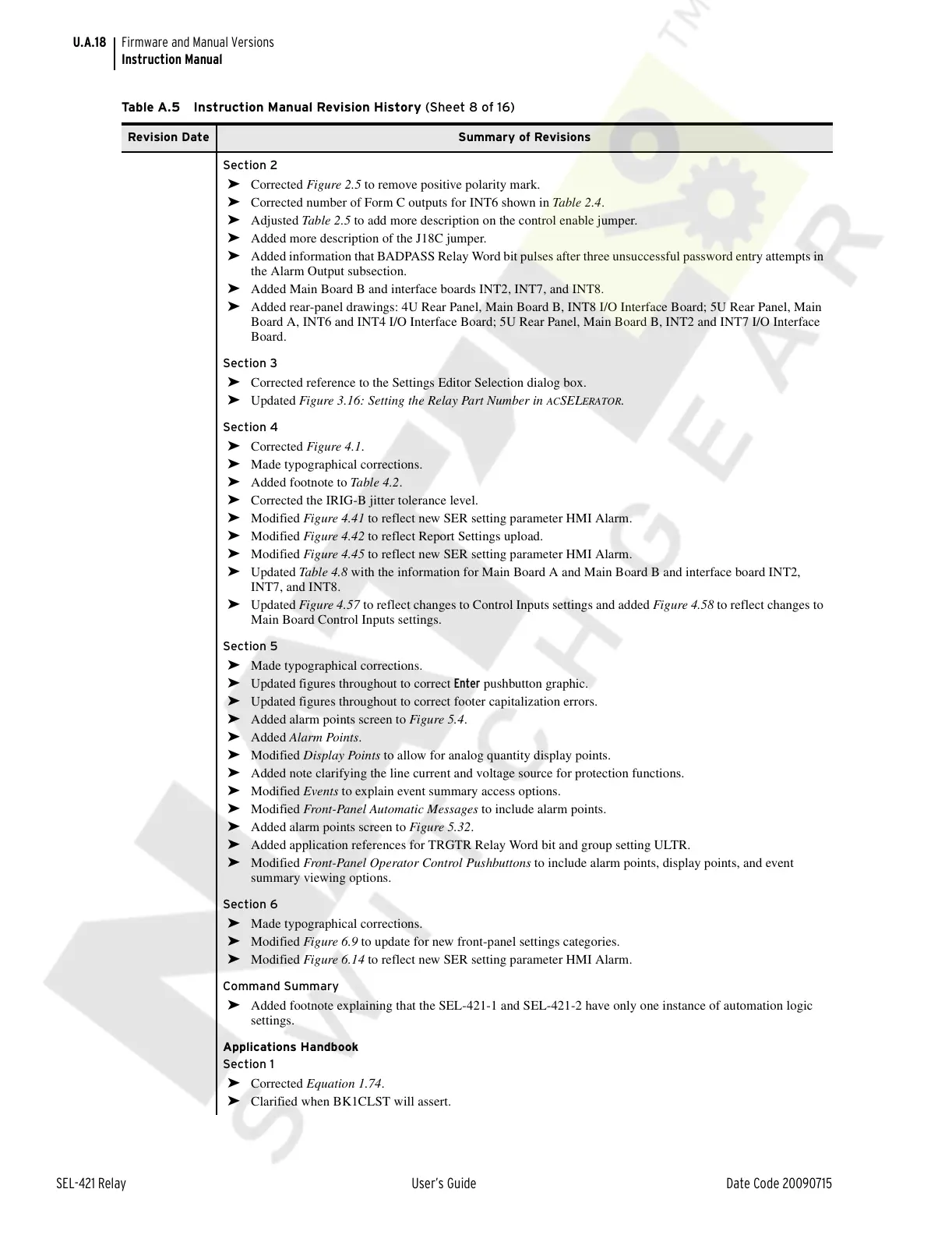
Section 2
➤ Corrected Figure 2.5 to remove positive polarity mark.
➤ Corrected number of Form C outputs for INT6 shown in Table 2.4.
➤ Adjusted Table 2.5 to add more description on the control enable jumper.
➤ Added more description of the J18C jumper.
➤ Added information that BADPASS Relay Word bit pulses after three unsuccessful password entry attempts in
the Alarm Output subsection.
➤ Added Main Board B and interface boards INT2, INT7, and INT8.
➤ Added rear-panel drawings: 4U Rear Panel, Main Board B, INT8 I/O Interface Board; 5U Rear Panel, Main
Board A, INT6 and INT4 I/O Interface Board; 5U Rear Panel, Main Board B, INT2 and INT7 I/O Interface
Board.
Section 3
➤ Corrected reference to the Settings Editor Selection dialog box.
➤ Updated Figure 3.16: Setting the Relay Part Number in ACSELERATOR.
Section 4
➤ Corrected Figure 4.1.
➤ Made typographical corrections.
➤ Added footnote to Table 4.2.
➤ Corrected the IRIG-B jitter tolerance level.
➤ Modified Figure 4.41 to reflect new SER setting parameter HMI Alarm.
➤ Modified Figure 4.42 to reflect Report Settings upload.
➤ Modified Figure 4.45 to reflect new SER setting parameter HMI Alarm.
➤ Updated Table 4.8 with the information for Main Board A and Main Board B and interface board INT2,
INT7, and INT8.
➤ Updated Figure 4.57 to reflect changes to Control Inputs settings and added Figure 4.58 to reflect changes to
Main Board Control Inputs settings.
Section 5
➤ Made typographical corrections.
➤ Updated figures throughout to correct Enter pushbutton graphic.
➤ Updated figures throughout to correct footer capitalization errors.
➤ Added alarm points screen to Figure 5.4.
➤ Added Alarm Points.
➤ Modified Display Points to allow for analog quantity display points.
➤ Added note clarifying the line current and voltage source for protection functions.
➤ Modified Events to explain event summary access options.
➤ Modified Front-Panel Automatic Messages to include alarm points.
➤ Added alarm points screen to Figure 5.32.
➤ Added application references for TRGTR Relay Word bit and group setting ULTR.
➤ Modified Front-Panel Operator Control Pushbuttons to include alarm points, display points, and event
summary viewing options.
Section 6
➤ Made typographical corrections.
➤ Modified Figure 6.9 to update for new front-panel settings categories.
➤ Modified Figure 6.14 to reflect new SER setting parameter HMI Alarm.
Command Summary
➤ Added footnote explaining that the SEL-421-1 and SEL-421-2 have only one instance of automation logic
settings.
Applications Handbook
Section 1
➤ Corrected Equation 1.74.
➤ Clarified when BK1CLST will assert.
Table A.5 Instruction Manual Revision History (Sheet 8 of 16)
Revision Date Summary of Revisions
Courtesy of NationalSwitchgear.com