08/2005 Starting Up HMI Embedded (IM2)
4 Functions/Parameterization
© Siemens AG, 2005. All rights reserved
SINUMERIK 840D sl/840D/840Di/810D HMI Installation and Start-Up Guide (IAM) – 08/2005 Edition
IM2/4-35
4.1.2 Keylock switch
Protection levels 4 to 7 require a corresponding keyswitch position on the machine
control panel. Three keys of different colors are provided for this purpose. Each of
these keys provides access only to certain areas. The keyswitch positions are
transferred at the PLC interfaces. The associated interface signals are in the DB10,
DBB56 and can be evaluated by the PLC user program.
Keyswitch application
The keyswitch can be used to inhibit access to certain data areas. In this way, for
example, unintentional changes by the operator in the geometry data (e.g., work
offsets) can be excluded.
Keyswitch position 0 has access rights of the lowest priority and position 3 access
rights of the highest priority.
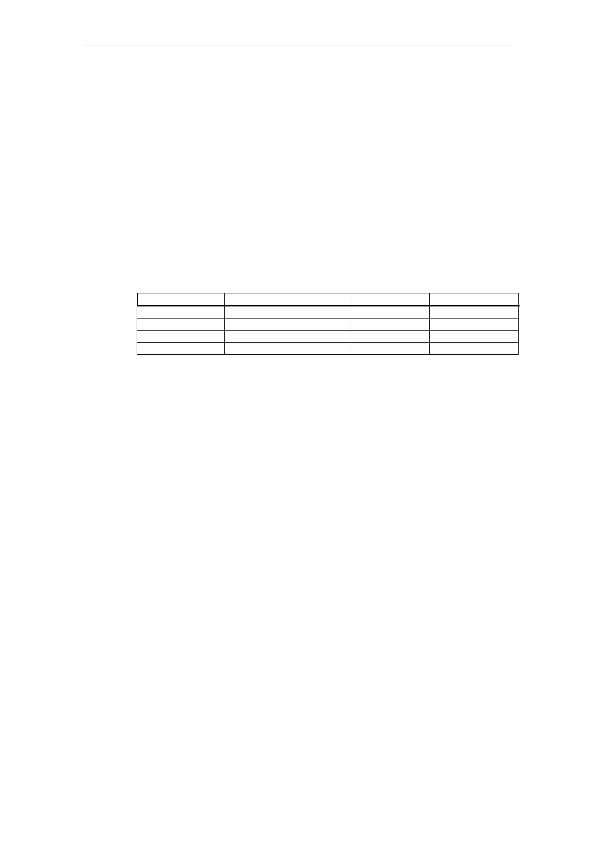
Table 4-2 Meaning of the keyswitch positions
Key color Switch position DB10, DBB56 Protection level
All (no key used) 0 = Key removal position Bit 4 7
Black 0 and 1 Bit 5 6-7
Green 0 to 2 Bit 6 5-7
Red 0 to 3 Bit 7 4-7
Influencing the PLC user program
The PLC interface signals "Keyswitch positions 0 to 3" can be input either directly
via the keyswitch on the machine control panel or from the PLC user program. If
more than one interface signal is set at the same time, the control sets keyswitch
position 3.
Redefining protection levels for NC data
The user can change the priority of the protection levels. Only protection levels of
lower priority can be assigned to the machine data, setting data can also be
assigned protection levels of higher priority.
Example:
%_N_SGUD_DEF ; File for global variables
; $PATH=/_N_DEF_DIR
REDEF $MA_CTRLOUT_SEGMENT_NR APR 2 APW 2
; (APR … read access)
REDEF $MA_ENC_SEGMENT_NR APR 2 APW 2
; (APW … write access)
REDEF $SN_JOG_CONT_MODE_LEVELTRIGGRD APR 2 APW 2
M30
The file becomes active when the next _N_INITIAL_INI is read in. Different
protection levels are specified for writing (changing) or reading (parts program or
PLC).

 Loading...


